System and method for dynamically adjusting cell sectorization

Active Publication Date: 2005-08-30
F POSZAT HU
View PDF14 Cites 69 Cited by
  • Summary
  • Abstract
  • Description
  • Claims
  • Application Information

AI Technical Summary

Benefits of technology

[0011]In CDMA systems, the FLMA preferably measures a parameter called the pilot-to-interference ratio. This parameter is generally a measurement of the ratio of the pilot signal power to the interference signal power. A CDMA pilot signal is usually a known signal with a known power that basically defines the boundaries of a sector. It is also typically used by the mobile device to decode the transmitted channel. However, when it is received by a mobile device, it has experienced environmental scattering effects such as fading and also is aff

Problems solved by technology

Heavy site traffic may have the undesirable consequence of causing some calls or communication links to be dropped, thus, decreasing the reliability and efficiency of th

Method used


Image

  • System and method for dynamically adjusting cell sectorization
  • System and method for dynamically adjusting cell sectorization
  • System and method for dynamically adjusting cell sectorization

Examples


Embodiment Construction

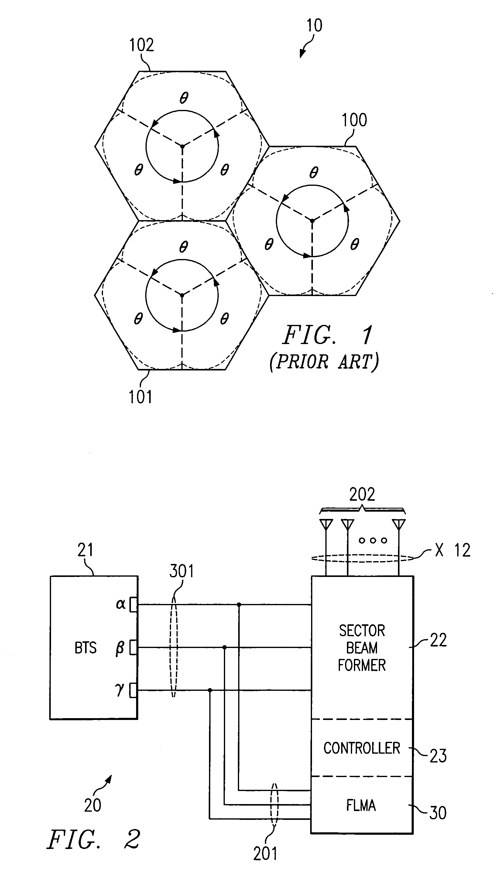
[0022]FIG. 1 illustrates three cells of a typical fixed sectorization scheme as found in prior art cellular communication systems. System 10 is divided into three individual cells 100–102. Each cell is further divided into three sectors. As is typical in the prior art, θ represents the angle defining the sectorization of the entire cell and network. Cells 100–102 each are sectorized into equal sectors each covering 120° (i.e., θ=120°). The sectors of the prior art systems generally remain fixed regardless of changing environmental or sector load conditions.

[0023]FIG. 2 illustrates a preferred embodiment of the present invention.

[0024]Communication system 20, such as may comprise cellular base transceiver station (BTS) radios 21 having three sector outputs, alpha (α), beta (β), and gamma (γ), which are input to sector beam former 22. Sector beam former 22 of the illustrated embodiment includes controller 23 and forward link monitoring assembly (FLMA) unit 30. Controller 23 may typica...


PUM


Abstract

The invention discloses a system and method which quantifies the traffic or load on a particular sector of a mobile communication cell site. The traffic quantification or load metric is preferably used to compare the load of each of the cell site's sectors. When the difference between load among the sectors reaches a certain level, the preferred embodiment of the present invention causes the sectorization of the site to change in order to alleviate or equalize the traffic load of the sectors. The system of the present invention continues to monitor the cell site for traffic conditions and for changes in the load responsive to the sectorization changes made in order to dynamically respond to the changing traffic conditions on the cell site.

Description

RELATED APPLICATIONS[0001]Reference is hereby made to the following concurrently-filed, co-pending, commonly assigned, U.S. patent application Ser. No. 09 / 930,523 entitled, “DYNAMIC AND SELF-OPTIMIZING SMART NETWORK;” and to commonly assigned, co-pending U.S. patent applications: Ser. No. 08 / 924,285, entitled, “ANTENNA DEPLOYMENT SECTOR CELL SHAPING SYSTEM AND METHOD,” filed on Sep. 5, 1997 and now issued as U.S. Pat. No. 6,246,674; Ser. No. 09 / 384,306, entitled, “ANTENNA DEPLOYMENT SECTOR CELL SHAPING SYSTEM AND METHOD,” filed on Aug. 26, 1999; and Ser. No. 09 / 393,124, entitled, “INPUT SPECIFIC INDEPENDENT SECTOR MAPPING,” filed on Sep. 10, 1999, the disclosures of which are incorporated herein by reference.TECHNICAL FIELD[0002]This invention relates to wireless communication systems and, in particular, to a signal radiation network of a wireless communication system which can be dynamically adjusted in response to changing network load and / or environmental conditions.BACKGROUND[00...

Claims


Application Information

Patent Timeline
IPC IPC(8): H04Q7/20H04W16/06H04W16/24
CPCH04W16/06H04W16/24
Inventor GORDON, SCOT D.YEA, JI-HAEFEUERSTEIN, MARTIN J.LIU, JUN
Owner F POSZAT HU
Why Eureka
Try Eureka