Sensor for transcutaneous measurement of vascular access blood flow

a technology of vascular access and blood flow, which is applied in the direction of instruments, catheters, applications, etc., can solve the problems of inconvenient and time-consuming reversal of dialysis blood lines from their normal configuration, high cost of procedures, and inability to perform early attempts to use indicator dilution methods

Inactive Publication Date: 2005-08-30
HEMA METRICS
View PDF78 Cites 11 Cited by
  • Summary
  • Abstract
  • Description
  • Claims
  • Application Information

AI Technical Summary

Benefits of technology

[0009]It is another object of the present invention to provide an optical hematocrit sensor that can detect changes in hematocrit transcutaneously.
[0010]It is still another object of the invention to pr

Problems solved by technology

The traditional approach for determining the vascular access flow rate is by Doppler flow imaging; however, these procedures are expensive and cannot be performed during routine hemodialysis, and the results from this approach are dependent on the machine and operator.
These early attempts to use indicator dilution methods were limited to research applications since this approach could not be routinely performed during clinical

Method used


Image

  • Sensor for transcutaneous measurement of vascular access blood flow
  • Sensor for transcutaneous measurement of vascular access blood flow
  • Sensor for transcutaneous measurement of vascular access blood flow

Examples


first embodiment

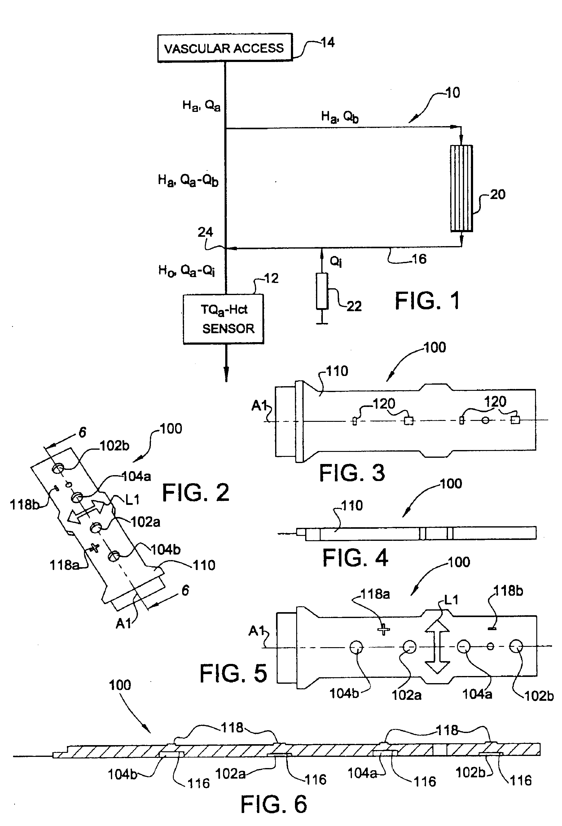
[0098]Referring now to FIGS. 2-6, there is shown the TQa sensor 100 in accordance with the present invention for the transcutaneous measurement of vascular access blood flow in a hemodialysis shunt or fistula 14. In this embodiment two emitters 102a and 102b and two detectors 104a and 104b are arranged in alignment along an axis A1 on a substrate 110. As mentioned above, this embodiment is employed if a gradient in αo exists in the area of interest (as is often the case in vivo), as multiple measurements must be made to establish the nature of the gradient and provide an averaged estimate of αo.

[0099]The sensor 100 has an access placement line L1 perpendicular to the axis A1. For proper operation, the sensor 100 must be placed with the access placement line L1 over the venous access site (shunt) 14. One of the emitters (the “inboard emitter”) 102a and one of the detectors (the “inboard detector”) 104a are placed at inboard positions on either side of and equidistant from the access ...

second embodiment

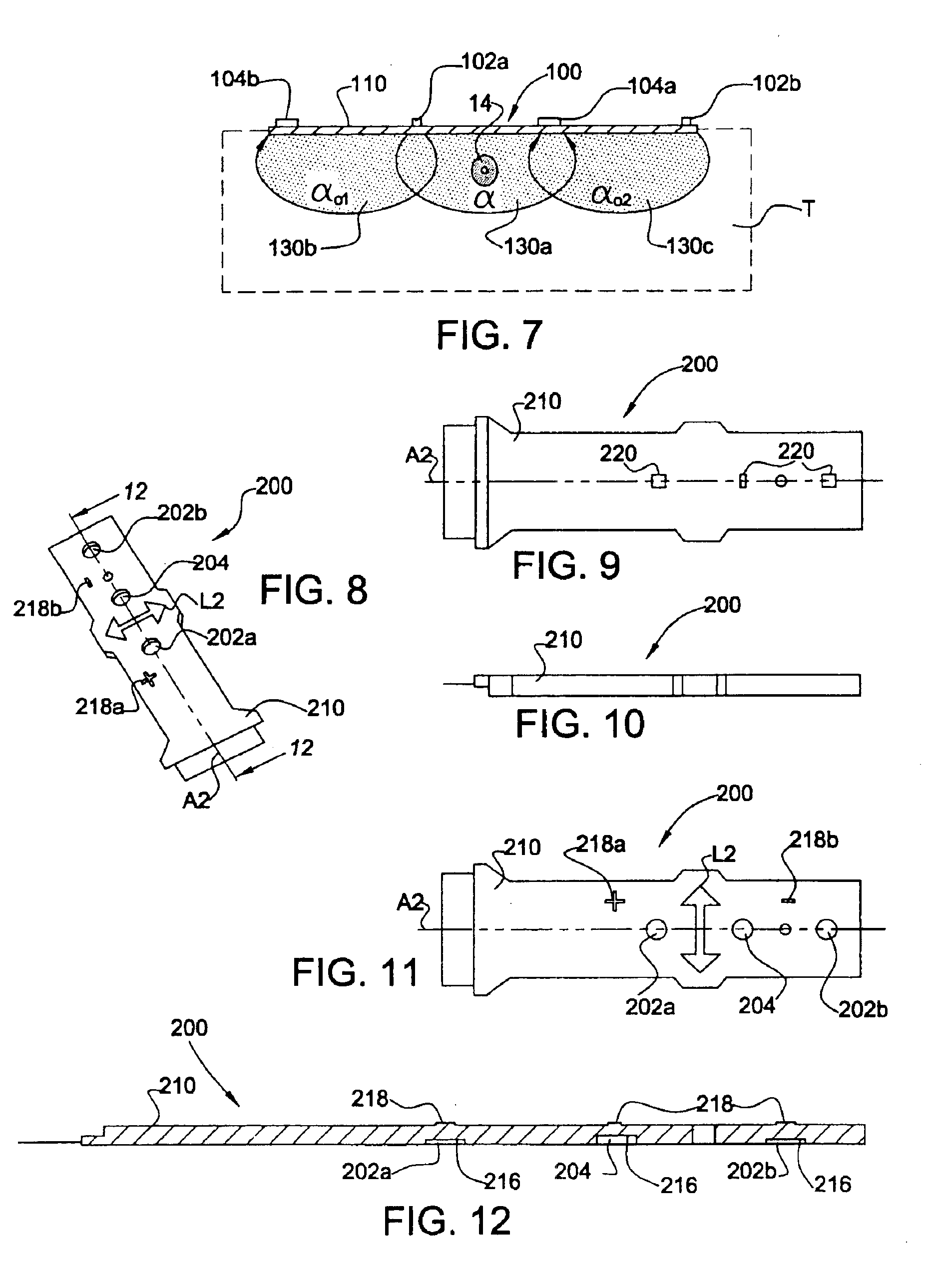
[0105]Referring now to FIGS. 8-12, there is shown the TQa sensor 200 in accordance with the present invention. In this embodiment two emitters 202a and 202b and one detector 204 are arranged in alignment along an axis A2 on a substrate 210. As mentioned above, this embodiment is employed if the tissue, T, is more or less homogenous, and it is only necessary to make a single reference αo measurement.

[0106]The sensor 200 has an access placement line L2 perpendicular to the axis A2. One of the emitters (the “inboard emitter”) 202a and the detector 204 are placed at inboard positions on either side of and equidistant from the access placement line L2. The second emitter (the “outboard emitter”) 202b is placed at a position outboard of the detector 204, so that the emitters 202a and 202b and the detector 204 alternate. The spacing between the emitters 202a and 202b and the detector 204 is uniform.

[0107]The substrate 210 is provided with apertures 216 in its lower surface for receiving th...

fourth embodiment

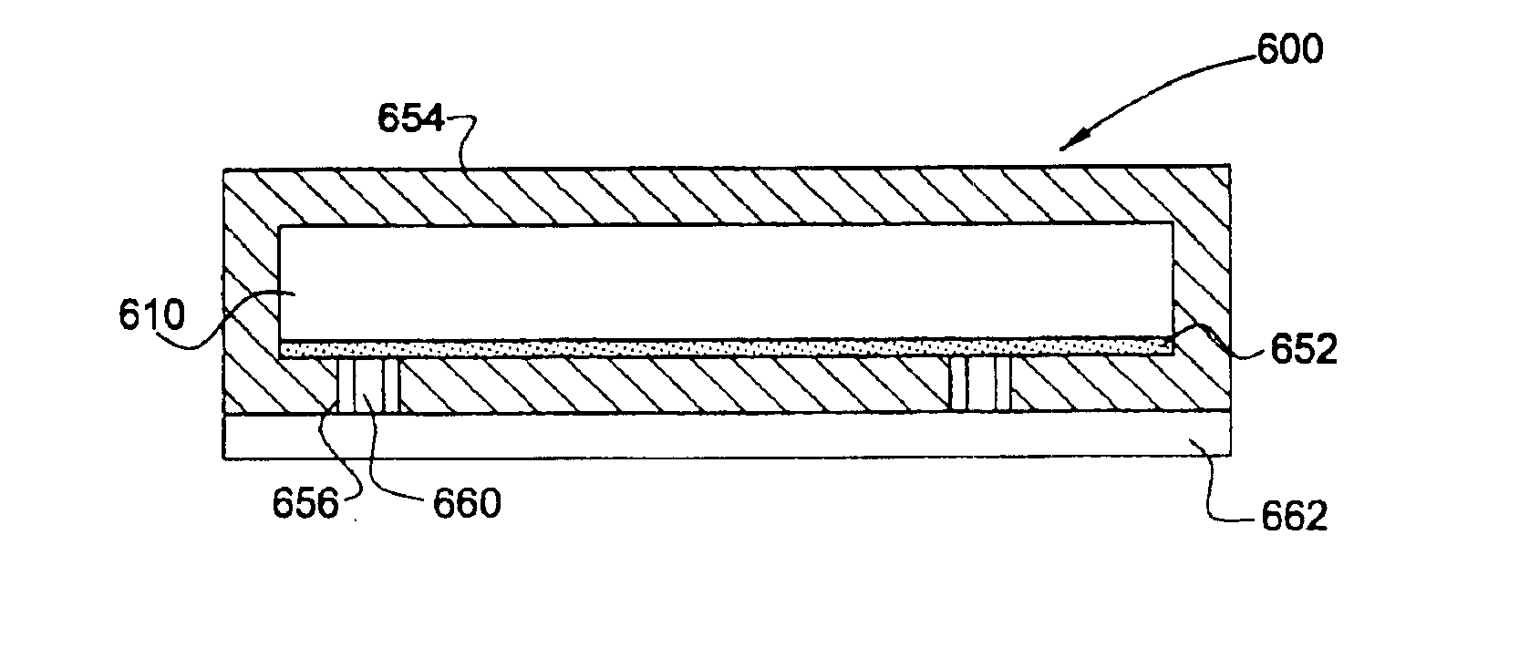
[0119]In the TQa sensor 400 in accordance with the fourth embodiment, the circuitry associated with the emitters 402a and 402b and the detectors 404a and 404b is also incorporated in the flexible components layer 410. The components layer 410 has a lower surface that faces the access site 14, and an upper surface that faces away. The emitters 402a and 402b and the detectors 404a and 404b may protrude from the lower surface of the components layer 410. A cover layer 412 of flexible foam or the like covers the upper surface of the components layer 410. A spacer layer 414 of flexible foam or the like covers the lower surface of the components layer 410, and has apertures 416 in registration with the emitters 402a and 402b and the detectors 404a and 404b, so that each emitter and detector is received in its own corresponding aperture 416. The spacer layer 414 has an upper surface that contacts the lower surface of the components layer 410 and a lower surface that faces away from the com...


PUM


Abstract

An optical sensor includes photoemitter and photodetector elements at multiple spacings (d1, d2) for the purpose of measuring the bulk absorptivity (α) of an area immediately surrounding and including a hemodialysis access site, and the absorptivity (αo) of the tissue itself. At least one photoemitter element and at least one photodetector element are provided, the total number of photoemitter and photodetector elements being at least three. The photoemitter and photodetector elements are collinear and alternatingly arranged, thereby allowing the direct transcutaneous determination of vascular access blood flow.

Description

CROSS-REFERENCE TO RELATED APPLICATIONS[0001]The present patent application is a divisional of application Ser. No. 09 / 750,076, filed Dec. 29, 2000, are is incorporated herein by reference in its entirety.BACKGROUND OF THE INVENTION[0002]1. Field of the Invention[0003]The present invention relates to apparatus for non-invasively measuring one or more blood parameters. More specifically, the invention relates to apparatus for the transcutaneous measurement of vascular access blood flow. The invention can also be used for precise access location, as a “flow finder,” and also can be used to locate grafts and to localize veins in normal patients for more efficient canulatization.[0004]2. Related Art[0005]Routine determination of the rate of blood flow within the vascular access site during maintenance hemodialysis is currently considered an integral component of vascular access assessment. While the relative importance of vascular access flow rates and venous pressure measurements in de...

Claims


Application Information

Patent Timeline
IPC IPC(8): A61B5/026A61M1/36A61B5/0275A61B5/00A61M1/14G01N21/03
CPCA61B5/0261A61B5/14535A61B5/14546A61B5/14552A61B5/14557A61B5/6826A61B5/6838A61B5/6843A61M1/3663G01N21/0303A61M1/361A61M1/3612A61M1/3656A61B5/14532G01N2021/036A61B5/026
Inventor STEUER, ROBERT R.BELL, DAVID A.MILLER, DAVID R.
Owner HEMA METRICS
Why Eureka
Try Eureka