System for use of land fills and recyclable materials

a land fill and recycling technology, applied in the direction of supercritical condition processes, discharging methods of containers, separation processes, etc., can solve the problems of inability to apply models, inability to meet the needs of other materials, and inability to clean, etc., to achieve the effect of improving the economic performance of the system

Inactive Publication Date: 2005-09-06
COOL CLEAN TECH
View PDF18 Cites 22 Cited by
  • Summary
  • Abstract
  • Description
  • Claims
  • Application Information

AI Technical Summary

Benefits of technology

[0019]Gases are vented from a waste site such as a landfill, and the gases are separated into at least three streams comprising a hydrocarbon stream, a carbon dioxide stream, and a residue stream. At least a portion of the carbon dioxide stream and hydrocarbon stream can be liquefied or converted to a supercritical liquid. New uses of the effluent gas streams are desirably found within the economic Environment and local physical environment of the waste site, and preferably physically within or adjacent to the waste site to improve the economic performance of the system. At least some of the carbon dioxide gas stream (as a liquid or supercritical fluid) may be used in a cleaning step, preferably a polymer cleaning step, and more preferably a polymer cleaning step in a polymer recycling process, and most preferably in a polymer cleaning step in a polymer recycling system where the cleaning is performed preferably on-site at the waste site or in direct pipeline connection to the carbon dioxide source in the waste site. Hydrocarbon gas may be used at least in part to generate energy at the site (e.g., by burning to create heat / thermal energy, to drive a motor or engine, or to generate electricity), provide a hydrogen fuel source, provide carbon black and the like.

Problems solved by technology

The limitations on this system included at least the facts that the containers would show unacceptable levels of wear fairly early during repeated reuse (especially with bottles that could be easily scratched or chipped), containers had to be returned to individual original suppliers according to brand names (which dictated against any centralized system), and cleaning was difficult as different co-wastes were added to the containers (e.g., cigarette stubs and filters) and few viable cleaning processes could remove some of the associated wastes without extensive manual labor.
This model, however, does not translate well to other materials, as the properties, economics, technology and market for aluminum are unique, and it is this uniqueness that enables success of the system.
This system is complicated in that associated wastes with differing sources of polymeric materials may not be amenable to a single format of treatment.
Although local jurisdictions may require some level of cleaning of the polymeric containers, the original liquids or powders may be insufficiently removed from the polymer.
A single cleaning process has been unlikely to act on all polymeric containers, at least in part because of the deficiencies in the cleaning steps that fail to provide a sufficiently pure supply of polymer that would enable direct recycling.
However, residual oil coating the interior surface of the “empty” motor oil containers constitutes a contaminant that prevents use of the containers as high grade plastics.
However, because the motor oils have not been easily separated from the plastic containers, the vast majority of these containers are currently disposed of in landfills, leaking oils into the soil and groundwater, and occupying significant landfill volume.
The problems with these options are as follows:a. Existing recyclers in the United States can blend limited quantities of oil contaminated plastics in recycled plastic products.
Large quantities cannot be blended because of the undesirable effects of the residual oil on the recycled plastic properties.
A stream of usable oil-free plastic will be generated by this method; however, the displaced oil will be contaminated or changed chemically and additional processing will be needed to separate it from the aqueous solutions.
In general, it is difficult to fully reclaim usable oil from the distillate.
Furthermore, many halogenated solvents are ozone depleting compounds and potential health hazards to humans, and therefore their use and release into the environment are under regulation and close scrutiny by federal and state governments.d.
Only distillation equipment suitable for combustible or flammable solvents may be used and even then fire safety concerns will be significant.
As in the case of the use of halogenated solvents, the oil may not be fully recoverable from the distillation.
However, they will provide usable oil only at the expense of a secondary waste stream that itself will require treatment and additional expense.
The recycling of plastic and oil from “empty” plastic oil containers presents serious environmental and waste stream disposal problems if conventional organic or aqueous solvents are used for the separation of the plastic and oil.
Discarding of the containers as landfill waste also presents environmental problems in that the residual oil may eventually leach into soil and groundwater.
Landfills are little more than holes in the ground into which massive volumes of wastes are dumped, compacted and covered, with an unsupported expectation that the material will eventually decompose and be absorbed into the normal ecology.
This expectation is unsupported because excavations of earlier (19th and early 20th century) landfills have found that even paper products, including newspapers, are substantially intact (if not structurally pristine) over a time period where decomposition had been expected.
Present attempts to moderate the impact of landfills have met limited environmental and limited economic success.
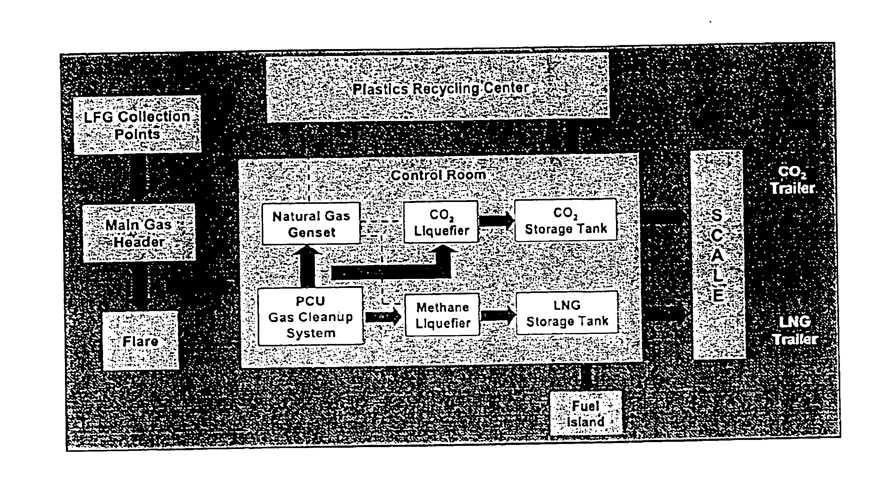
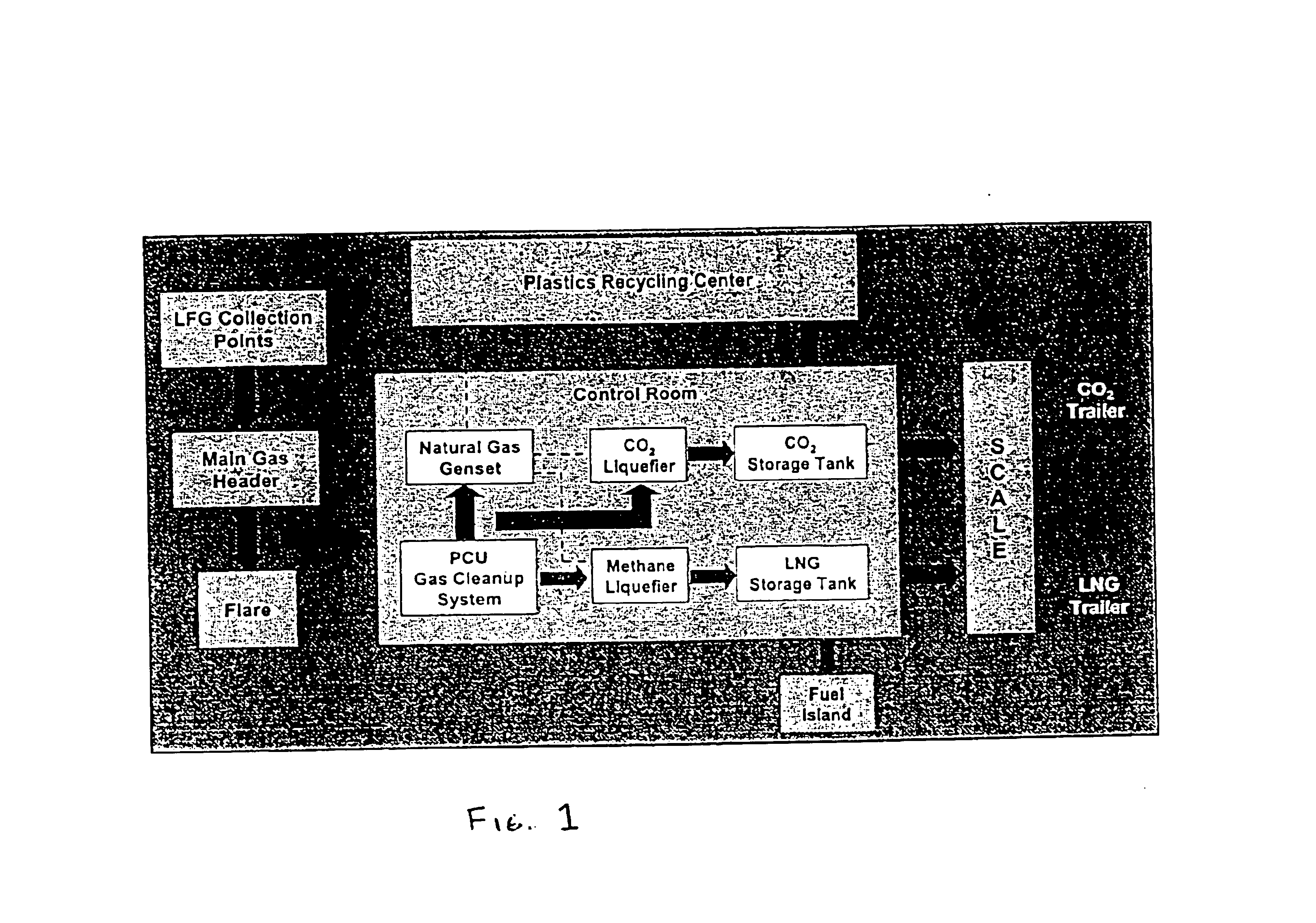
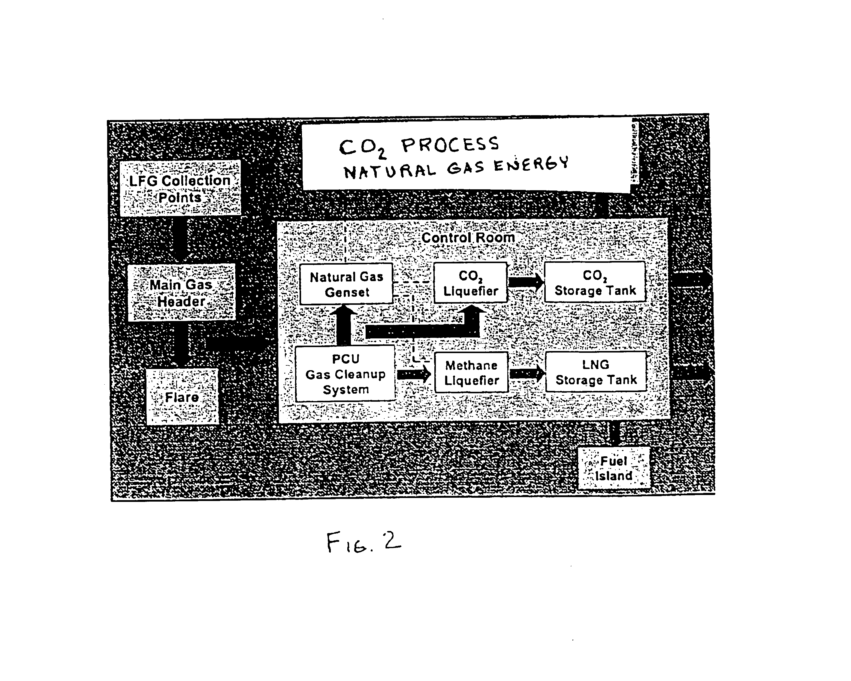
The carbon dioxide has also been liquefied, but has found few commercial outlets of sufficient volume as to make that product stream economically supportive of the recycling process.
The first manufacturer to use this source of carbon dioxide would be quickly attacked in the market by its competitors, even though the carbon dioxide greatly exceeds the purity required by the industry.

Method used


Image

  • System for use of land fills and recyclable materials
  • System for use of land fills and recyclable materials
  • System for use of land fills and recyclable materials

Examples


Embodiment Construction

[0024]One aspect of the present invention is to provide a more economically viable system associated with landfills. In the absence of greater economic benefits to the owners and investors in landfills, the ability of landfills to assist in actual waste reduction is limited. It is therefore necessary to associate additional technologies to existing and future landfill sites and or MRFs (material recovery facility) to assure maximum use of the materials at the site that can be used in subsequent commercial processes. This use of available resources includes the addition of commercial systems to the recycling sites and the use of effluent gases in existing and developing commercial processes. The fact that in most jurisdictions recycling and landfill sites are closely aligned can assist in the improvement in landfill utilization, as the recycled materials (e.g., paper, plastic, and metals such as aluminum and steel) and the waste material (for the landfill) are already brought to a co...


PUM


Abstract

Gases are vented from a waste site such as a landfill, and the gases are separated into at least three streams comprising a hydrocarbon stream, a carbon dioxide stream, and residue stream. At least a portion of the carbon dioxide stream and hydrocarbon stream are liquefied or converted to a supercritical liquid. At least some of the carbon dioxide gas stream (as a liquid or supercritical fluid) is used in a cleaning step, preferably a polymer cleaning step, and more preferably a polymer cleaning step in a polymer recycling process, and most preferably in a polymer cleaning step in a polymer recycling system where the cleaning is performed on-site at the waste site.

Description

BACKGROUND OF THE INVENTION[0001]1. Field of the Invention[0002]The present invention relates to the use of gas within land-fill sites, the recycling of materials from recycling collection and separation, and the recycling or commercial use of waste effluents materials from land-fills.[0003]2. Background of the Art[0004]The most significant societal effect caused by the unceasing growth in world human population is the increased use of a limited supply of raw materials. Both in the field of agricultural and the field of commercial products, an increasing population requires an increasing expenditure of energy and use of material to sustain even the existing average life style. As desires and expectations are growing around the world within every population center for higher standards of living, there is a multi-faceted draining effect on resources. Increased production capacity has been able to sustain this growth for centuries, but even the most optimistic technologist must appreci...

Claims


Application Information

Patent Timeline
Patent Type & Authority Patents(United States)
IPC IPC(8): B01D53/22B01D53/02B01D53/14B01D53/00B09B1/00B08B7/00F25J1/02F25J1/00B01J3/00
CPCB01D53/00B01D53/02B01D53/14B01D53/22B01J3/008B08B7/0021B09B1/00F25J1/0022F25J1/0027F25J1/0283B01D53/002Y10T428/2495C01B2203/06F25J2210/66F25J2290/60Y02E60/321Y10S62/929Y10T428/24942Y02E60/32Y02P20/54
Inventor WIKSTROM, JON P.SCHILLER, DANTURNER, JON R.
Owner COOL CLEAN TECH
Why Eureka
Try Eureka