
Isolation technique for pressure sensing structure

a technology of pressure sensing structure and isolation technique, which is applied in the direction of fluid pressure measurement, fluid pressure measurement by electric/magnetic elements, instruments, etc., can solve the problems of conductive and corrosive fluids (gases and liquids) damaging the sensor and electronic structure, and the sensor can be easily damaged, so as to improve the reliability and cost of the sensor package, the effect of reducing the volume of oil in the oil-filled cavity and enduring high vacuum

Inactive Publication Date: 2005-09-06
MEASUREMENT SPEC
View PDF34 Cites 49 Cited by
  • Summary
  • Abstract
  • Description
  • Claims
  • Application Information

AI Technical Summary

Benefits of technology

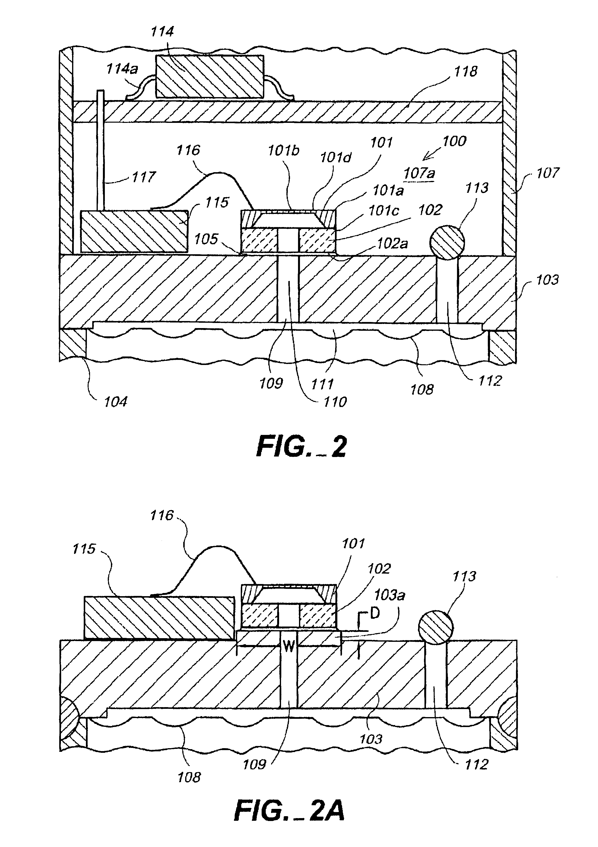
[0018]In one embodiment, a second side of the die contacts oil in an oil-filled cavity, The die is bonded and sealed to a plate (i.e. a leader) such that the oil is kept away from the first side of the die. Because of this, the volume of oil in the oil-filled cavity can be greatly reduced compared to the sensor of FIG. 1. This is because the oil-filled cavity does not have to be large enough to surround the die and house bonding wires and pins coupled thereto. In particular, the cavity does not have to be large enough to accommodate pins that are hermetically sealed to the header. Further, the oil-filled cavity does not have to be large enough to accommodate electrical assembly tolerances.
[0020]In one embodiment, the die is bonded to the header using a hermetic die attach material. By using a hermetic die attach material (e.g. glass, solder or braze), gas cannot be pulled through the adhesive. Because of the use of hermetic die attach material, the sensor package can withstands high vacuum for extended periods of time without suffering damage.

Problems solved by technology

Due to the hostile environment from highly corrosive fluids and the like, packages for electronic sensors measuring pressures in such environments are typically highly specialized, difficult to calibrate and expensive.
A drawback to MEMS sensors is that conductive and corrosive fluids (gases and liquids) can damage the sensor and the electronic structures (e.g. resistors) that are used to measure the pressure.
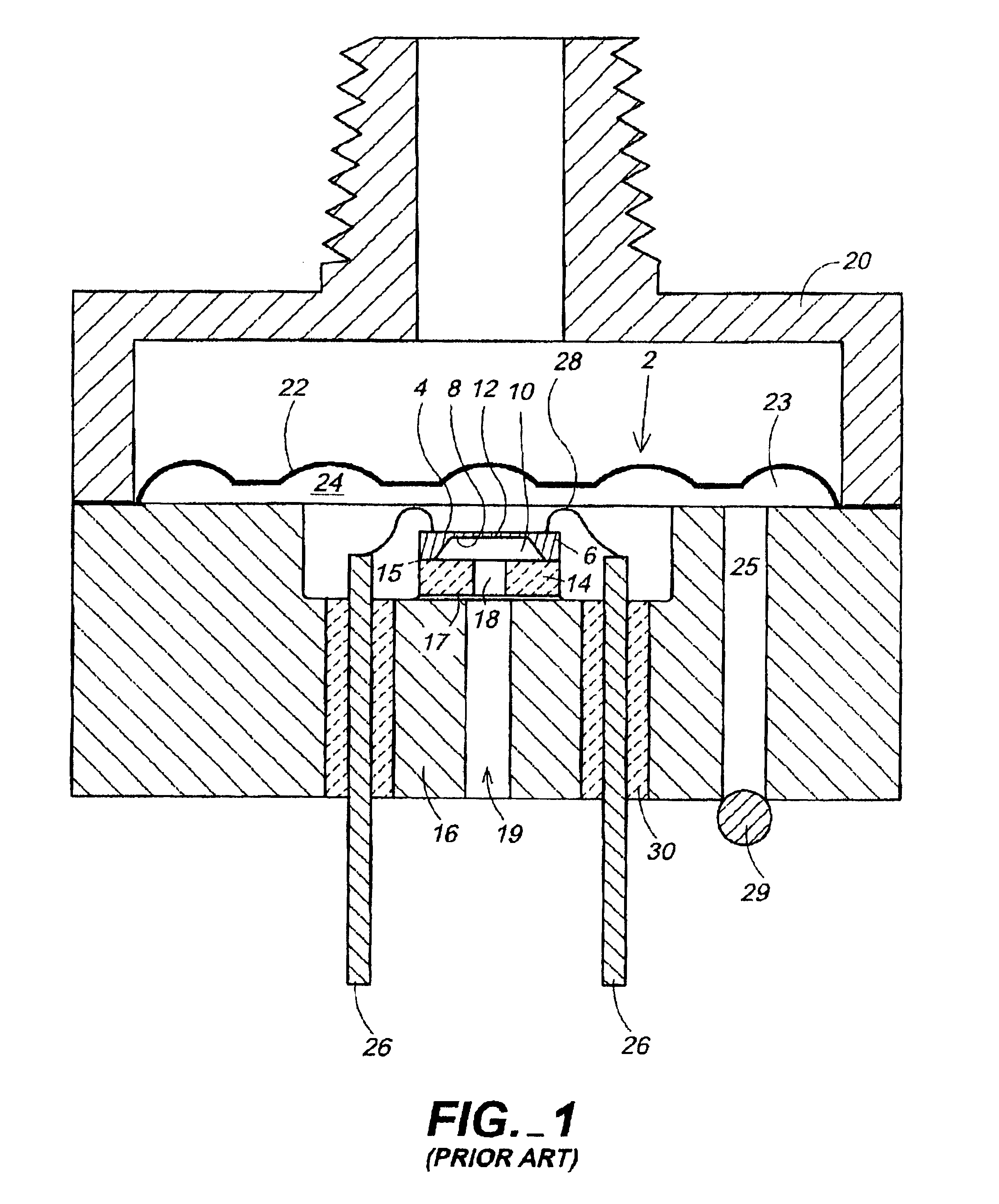
A significant drawback the design of FIG. 1 is that when the temperature is increased, oil 24 expands and exerts pressure on stainless steel diaphragm 22 and sensor die 6.
The resulting errors introduced into the sensor measurements may contain linear and nonlinear components, and are hard to correct.
Another drawback to this design arises out of the fact that die 6 is made of silicon, which has a low coefficient of thermal expansion.
A third drawback to this design is the fact that hermetic feedthrough pins 26 are costly and problematic.
These designs are difficult to customize and the hermetic seals can be a leak point that must be checked before the sensor is assembled.
Here, the amount of corrosion protection is limited because the sensor and associated seals are subject to damage by corrosive and possibly conductive materials.
Conformal coatings such as Parylene or silicone materials only provide minimal corrosion improvement.

Method used


Image

  • Isolation technique for pressure sensing structure
  • Isolation technique for pressure sensing structure
  • Isolation technique for pressure sensing structure

Examples


Embodiment Construction

[0032]While the invention is described below with reference to certain illustrated embodiments, it is understood that these embodiments are presented by way of example and not by way of limitation.

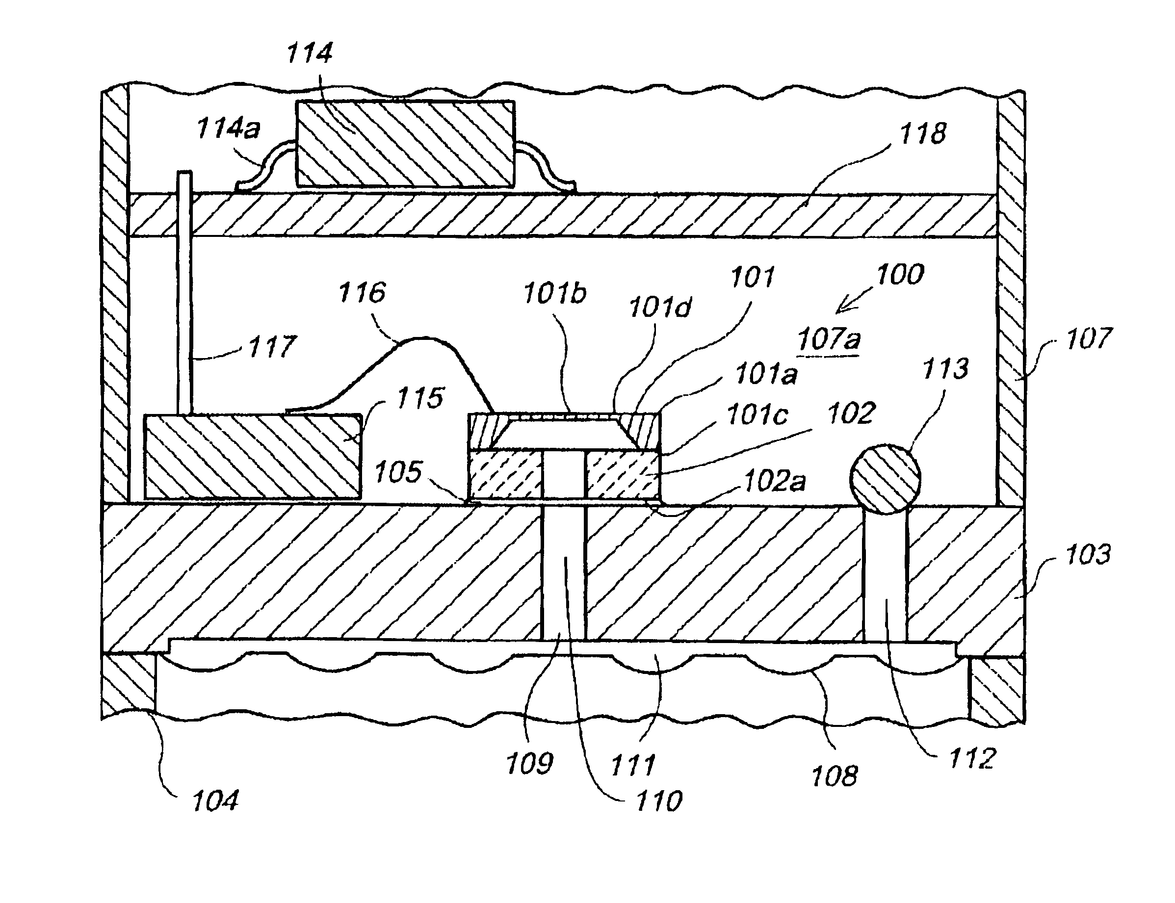
[0033]FIG. 2 illustrates in cross section a pressure sensor assembly 100 comprising a micro-machined silicon pressure sensor die 101 comprising a frame portion 101a surrounding a thinned diaphragm portion 101b. (Diaphragm portion 101b is typically formed by thinning a portion of a silicon wafer using either a liquid or dry etching process.) Piezoresistive resistors are formed in the top surface of die 101 in diaphragm portion 101b, e.g. by ion implantation or diffusion. These resistors are formed in locations on diaphragm 101b where the strain is greatest when diaphragm 101b is exposed to fluid under pressure.

[0034]Die 101 is anodically bonded to a support structure 102. Support structure 102 is sometimes referred to as a “constraint,” and is typically silicon or glass. In one embodiment, ...


PUM


Abstract

An electronic pressure-sensing device is isolated from corrosive, conductive gasses and fluids by a corrosion resistant metal diaphragm welded to a pressure port. The pressure-sensing device is attached to a support structure with a hole that provides a path from the diaphragm area to the pressure-sensing device. A fill fluid is sealed behind the diaphragm and fills the hole through the support structure to the electronic pressure-sensing device. In this design, any hostile chemical applied is completely isolated from the electronic sensor and associated adhesive seals by the metal diaphragm.

Description

[0001]This application is a continuation of U.S. patent application Ser. No. 09,489,560, filed Jan. 19, 2000, now U.S. Pat. No. 6,550,337, incorporated herein by reference.BACKGROUND[0002]The present invention relates generally to pressure sensing transducers and pertains particularly to a package for transducers that is resistant to corrosive or conductive gasses and liquids.[0003]Due to the hostile environment from highly corrosive fluids and the like, packages for electronic sensors measuring pressures in such environments are typically highly specialized, difficult to calibrate and expensive.[0004]A pressure sensor (or pressure transducer) converts pressure to an electrical signal that can be easily measured. Sensors that incorporate micro-machining or MEMS (Micro-Electro-Mechanical System) technology are small and very accurate. Because they are fabricated similarly to the fabrication of commercial semiconductors they are also inexpensive to produce. FIG. 1 illustrates a MEMS p...

Claims


Application Information

Patent Timeline
IPC IPC(8): G01L7/02G01L9/00G01L7/08
CPCG01L9/0042G01L19/0069G01L19/0645G01L19/147G01L19/146H01L2224/48091H01L2224/48137H01L2224/48465H01L2224/73265H01L2924/15151H01L2924/00014
Inventor WAGNER, DAVID E.HOFFMAN, JAMES H.LOPOPOLO, GERALD
Owner MEASUREMENT SPEC
Learn More