Soil aerating machine

a technology aerator, which is applied in the field of soil aeration machine, can solve the problems of ineffective drain field, inability to adequately drain drain field, and high cost and process disruption, so as to reduce initial investment and unnecessary equipment, enhance maneuverability and control, and optimize performance

Active Publication Date: 2005-09-06
K&P ENTERPRISES
View PDF63 Cites 21 Cited by
  • Summary
  • Abstract
  • Description
  • Claims
  • Application Information

AI Technical Summary

Benefits of technology

[0012]A first object of the invention is to reduce the initial investment and unnecessary equipment required to aerate soil. A second object of the invention is to substantially enhance maneuverability and control over the placement of an earth penetrating air tube in the earth. Another object of the present invention is to provides high vo

Problems solved by technology

Unfortunately, over time a drain field may become ineffective.
The end result is normally highly compacted soil which is impervious to the passage of liquid, or which is sufficiently impervious th

Method used


Image

  • Soil aerating machine
  • Soil aerating machine
  • Soil aerating machine

Examples


Embodiment Construction

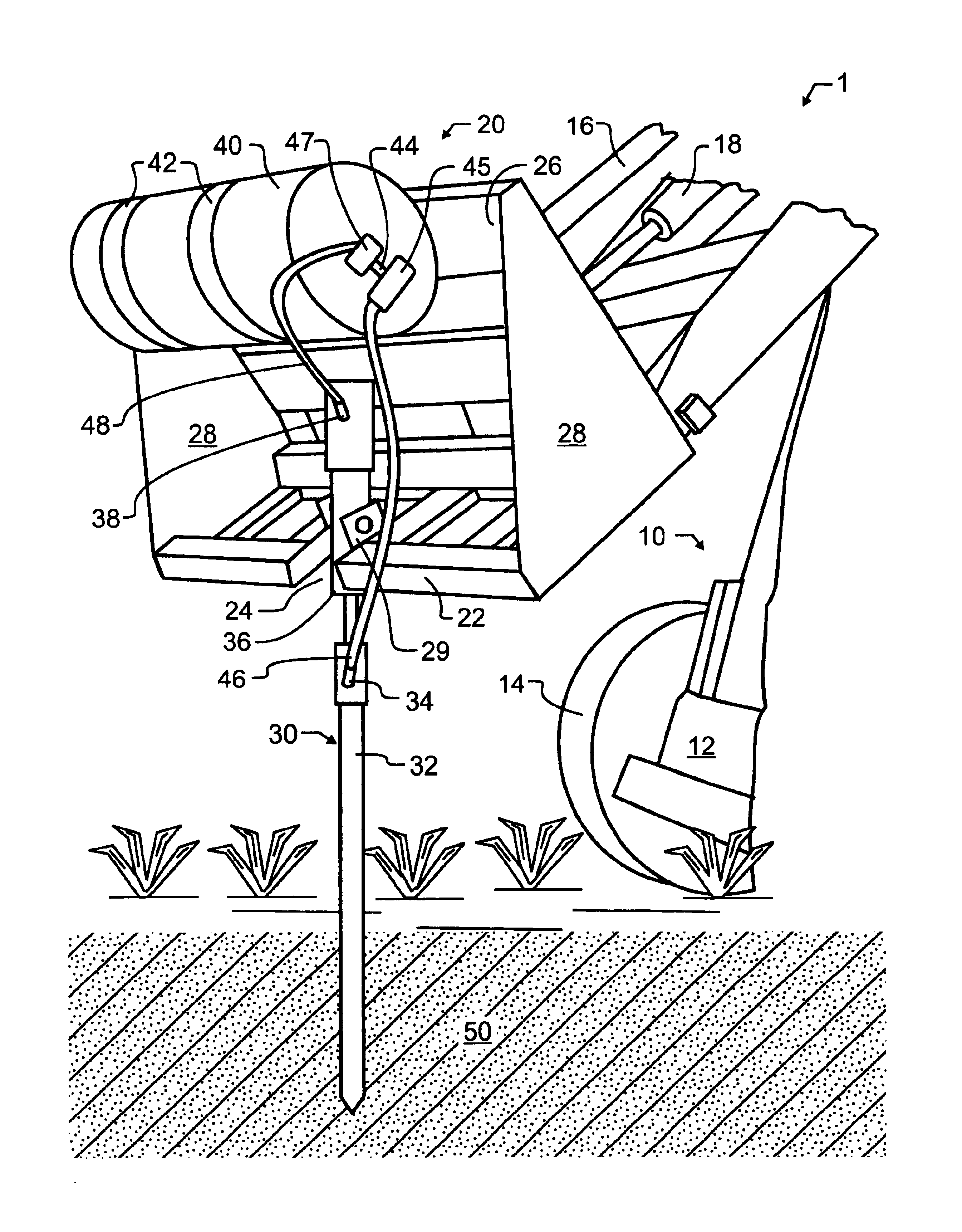
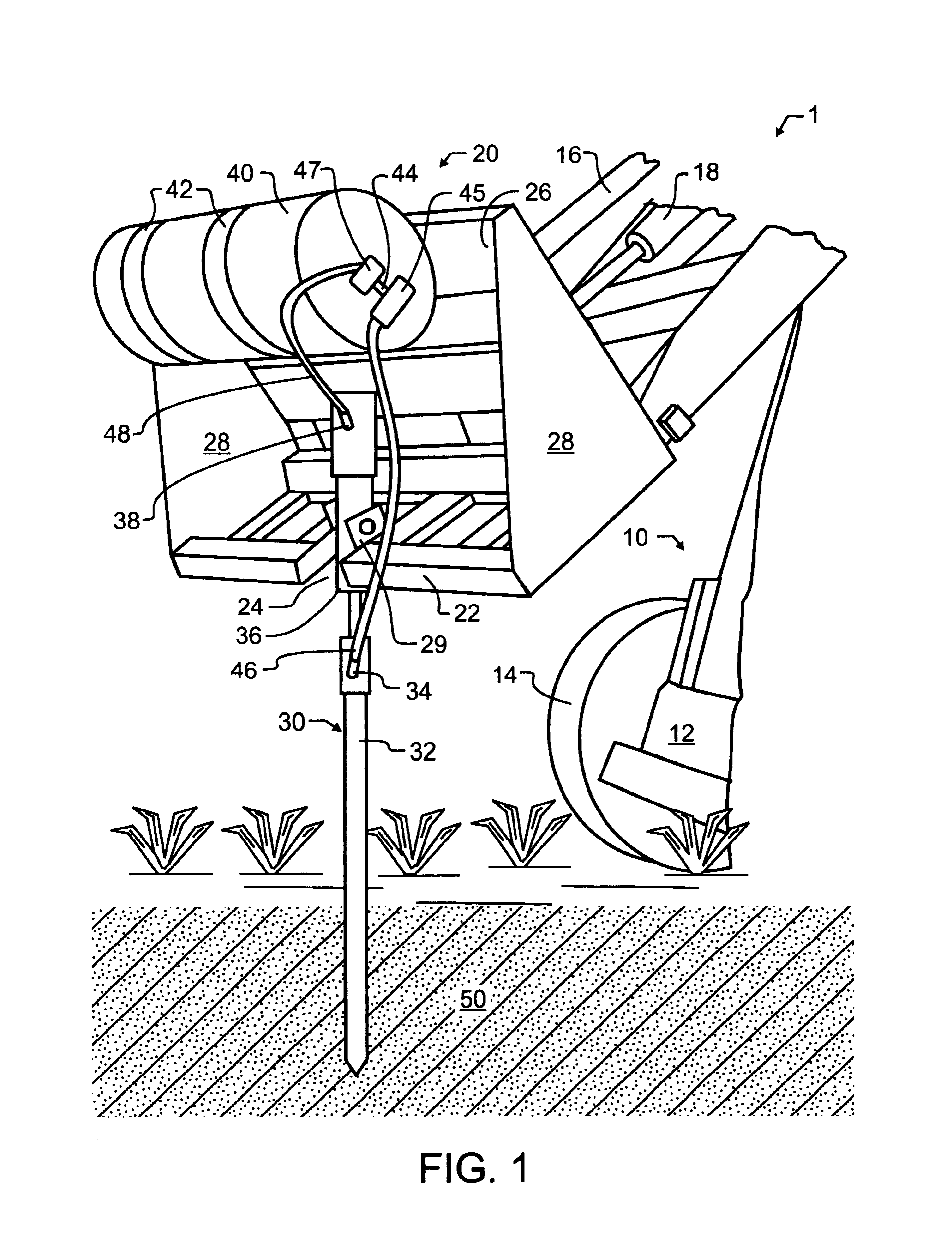
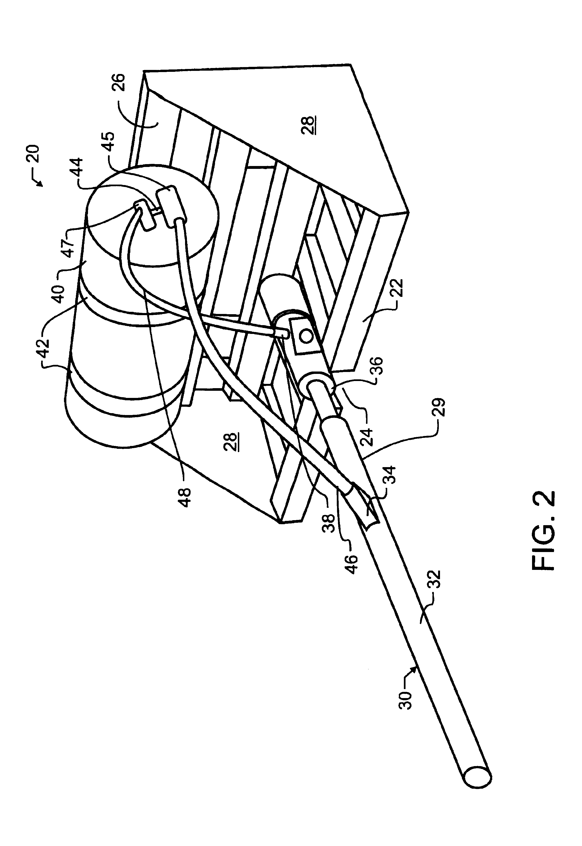
[0017]In a most preferred embodiment of the invention illustrated in FIG. 1, a soil aerating machine 1 includes in combination a small self-propelled vehicle 10 of the type adapted to manipulate and raise and lower a loader bucket, commonly referred to as a skid-steer, an air pressure tank 40, an elongate air nozzle tube or pipe 30, an air control valve 45, and an air hammer 36 used to assist with the driving of the elongate air nozzle pipe 30 into an earthen medium 50. In the preferred embodiment, air control valve 45 will be a low-voltage electrically controlled valve which may be actuated by movement of electric blast switch 4, which might typically be located within the operator's compartment or cage of self-propelled vehicle 10. Low voltage electrical actuation permits air control valve 45 to be driven from the electrical power normally available from a skid steer electrical system. Other techniques of actuating a valve, including in particular various pneumatic or hydraulic ap...


PUM


Abstract

A soil aerating machine includes in combination a skid-steer and a basket resembling a loader bucket adapted for attachment to the skid-steer boom. An air pressure tank, an elongate air nozzle pipe, an air hammer, and air control valves for the air nozzle pipe and air hammer are carried within the basket. The elongate air nozzle is attached to the basket using a pivotal bearing surface, which permits controlled motion therebetween. The air hammer is used to assist with the driving of the elongate air nozzle pipe into an earthen medium. A blast of air is then released through the air nozzle pipe into the earth, to loosen and aerate packed or clogged soil. A method of restoring a septic system using the preferred apparatus is also described, as are various alternative apparatus and method steps.

Description

CROSS REFERENCE TO RELATED APPLICATIONS[0001]This application claims priority to U.S. provisional patent application Ser. No. 60 / 428,789 filed Nov. 21, 2002 entitled “Soil Aerating Machine” and invented by the present inventor.BACKGROUND OF THE INVENTION[0002]1. Field of the Invention[0003]This invention pertains generally to the field of septic system maintenance, and more specifically to an apparatus useful in the restoration of failed or weakened septic systems.[0004]2. Description of the Related Art[0005]Septic systems are provided in many residences and businesses to safely manage solid and liquid wastes that may be produced. According to modern requirements, these systems are located relatively close to the top surface of the earth, in order to most efficiently utilize purification which is present in nature. A typical system may include a solids or settling tank, followed by a relatively expansive drain field. The drain field, depending upon local requirements, may be buried ...

Claims


Application Information

Patent Timeline
IPC IPC(8): B09C1/00A01B45/02
CPCA01B45/023B09C1/00
Inventor POSCH, GREGORY J.
Owner K&P ENTERPRISES
Why Eureka
Try Eureka