Spa and pool filter

a filter and pool technology, applied in the field of filters for liquids, can solve the problems of affecting the performance of the pump, affecting the affecting the flow rate of the cartridge filter, and achieve the effects of enhancing both the performance and life of the pump, and reducing the cost of production

Inactive Publication Date: 2005-09-06
ORIX CAPITAL MARKETS LLC
View PDF18 Cites 43 Cited by
  • Summary
  • Abstract
  • Description
  • Claims
  • Application Information

AI Technical Summary

Benefits of technology

[0014]The present invention is directed to an internal spa filter including a filter body and a complementary filter bag having a sheath which encompasses the exterior of the filter body and an internal pocket which extends into the filter body. The filter body is configured to be installed within a spa's water circulation system in order to filter particles and debris out of the water. As the spa water is circulated, through the filter body a vortex effect is created within the filter bag pocket trapping debris therein for later removal without the risk of the debris falling off the filter and back into the spa water. The configuration and materials of the spa filter of the present invention, as compared to the prior art filters, provide for much higher flow rates through the filter, further enhancing both the performance and life of the pump of the spa circulation system. Moreover, the spa filter of the present invention is relatively inexpensive to manufacture, whereby, after prolonged use, the filter bag itself may be either readily cleaned and reused or alternatively simply discarded.
[0022]In operation, after the sheath of the filter bag has been removably positioned in covering relationship over the filter body with the bag pocket extending into the filter body, the internal spa filter of the present invention is ready for use and is installed within the filter-receiving bay of a conventional spa with the filter in direct communication with the spa's circulation system on the suction side of the pump. Once the spa tub is filled with water and the circulation system is operated, the water is drawn through the filter by the pump. Because the inlet opening of the filter body, approximately 5½″ diameter, is relatively larger than the discharge orifice at the closed end of the filter body, which is typically on the order of about 2-3″, this difference in area will naturally create a vortex tending to draw the water down through the filter pocket, pulling larger debris into the pocket and trapping it there for later removal. The vortex action and the resulting strong suction of water through the filter also creates a vacuum pressure on the inside of the filter that serves to pull the filter bag's sheath tightly against the exterior of the filter body, thus effectively creating a tight fit between the sheath and the filter body which causes all water being pulled through the filter to pass through the filter bag.
[0023]The porosity of the filter bag material, the configuration of the open pocket, and the vortex effect cooperate to provide for higher flow rates through the filter (on the order of about 150 gallons per minute) as compared to conventional prior art spa filters. This increased flow rate translates to enhanced performance of the spa in terms of the relaxation and therapeutic benefits to the user and the life of the circulation pump.
[0024]When the filter bag of the present invention has become sufficiently dirty that it should be cleaned or replaced, the spa's circulation system is shut down and the filter bag is simply lifted out of the filter body by grasping the handle. The debris trapped by the filter during use will remain within the inside pocket, thereby not contaminating the spa water as the filter bag is removed from the filter-receiving bay. If the filter bag is removed from the spa to be cleaned for reuse, the bag is dumped or rinsed out to remove all debris that has been trapped or alternatively may be washed or laundered in a conventional washing machine and dryer to more thoroughly clean and sanitize the bag. If it is preferred that the filter bag be replaced rather than being cleaned, the used filter bag may be simply discarded and a new bag put into the filter body. Because the materials and construction methods employed in producing the filter of the present invention are relatively inexpensive, disposing of the filter bag is both a convenient and economical substitute for cleaning the bag.

Problems solved by technology

As the filter traps more and more solid particles, the pores in the filter media become clogged, inhibiting the flow of water through the pool or spa's circulation system and thereby decreasing performance and possibly even damaging the circulation pump.
Though the conventional cartridge filter is in wide use, there are still several shortcomings with this filter type that have not yet been overcome.
First, the flow rate through the cartridge filter is limited by the material and configuration of the pleats and the apertures in the rigid cylindrical core.
Second, despite the overall increased surface area of the filter material achieved by the pleats, only so much of this surface area is truly usable, as the folds of the pleat are tight and are butted up against the cylindrical core.
Moreover, as particles and debris become lodged between the pleats, the useful filter surface area that is lost is effectively doubled because the particles and debris clog pores on both adjacent surfaces of the pleat.
Thus, cartridge filters become clogged and experience decreased flow rates relatively quickly.
A third shortcoming of the cartridge filters known and used in the art is that they cannot be readily cleaned after becoming clogged.
Because of these inconveniences, some pool and spa owners simply use their cartridge filters until they become clogged and discard them, often prematurely, rather than bothering to clean them out.
Moreover, because cartridge filters trap debris on the outside of the filter only, when the filter is removed from the pool or spa for cleaning or disposal, it is possible that the debris that is loose and easily removed will fall off the filter into the clean side of the circulation system rather than being permanently removed.
These DE filters are relatively more expensive than comparable cartridge filters and may be subject to municipal or environmental authority regulations pertaining to cleaning and disposal.
However, the debris is not permanently captured by the sand filter medium and can eventually work its way through the filter and back into the pool or spa circulation system.
Sand filters, like the DE filters, are more costly than cartridge filters.
Based on the configuration and number of components in these prior art industrial bag-type filters, it follows that such filters are not well-suited for use in spas because of their complex design and inherent relatively high cost.
Furthermore, the housing, which plays a critical role in the function and performance of the prior art bag-type filters, is particularly ill-suited for use in a spa's circulation system because the conventional spa's filter-receiving cavity cannot accommodate the housing, and the housing itself, having only one small inlet strategically positioned above the location where the filter is sealed within the housing, would likely perform poorly under the changing water levels and other conditions of a pool or spa during use.

Method used


Image

  • Spa and pool filter
  • Spa and pool filter
  • Spa and pool filter

Examples


Embodiment Construction

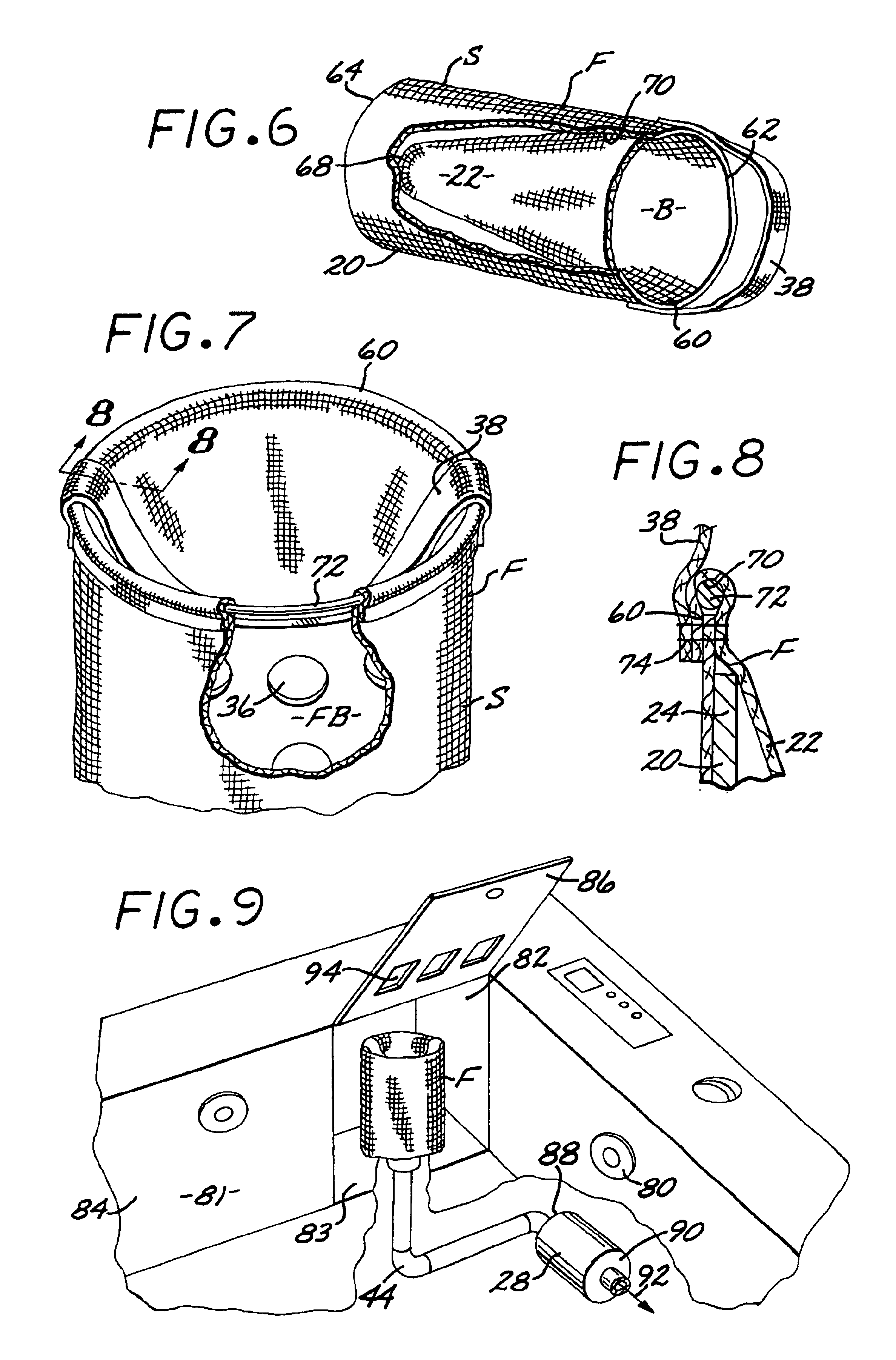
[0048]As shown in the drawings for purpose of illustration, an internal spa filter of the present invention utilizes a filter bag removably disposed upon a cylindrical filter body and configured to be installed within a spa's circulation system in order to filter particles and debris out of the spa water. While the spa filter embodying the present invention is described and depicted as being used in a conventional spa, it will be appreciated that the invention can also be used in conjunction with above- and below-ground swimming pools, hot tubs, Jacuzzis, or with any other system involving recirculated water that is to be filtered.

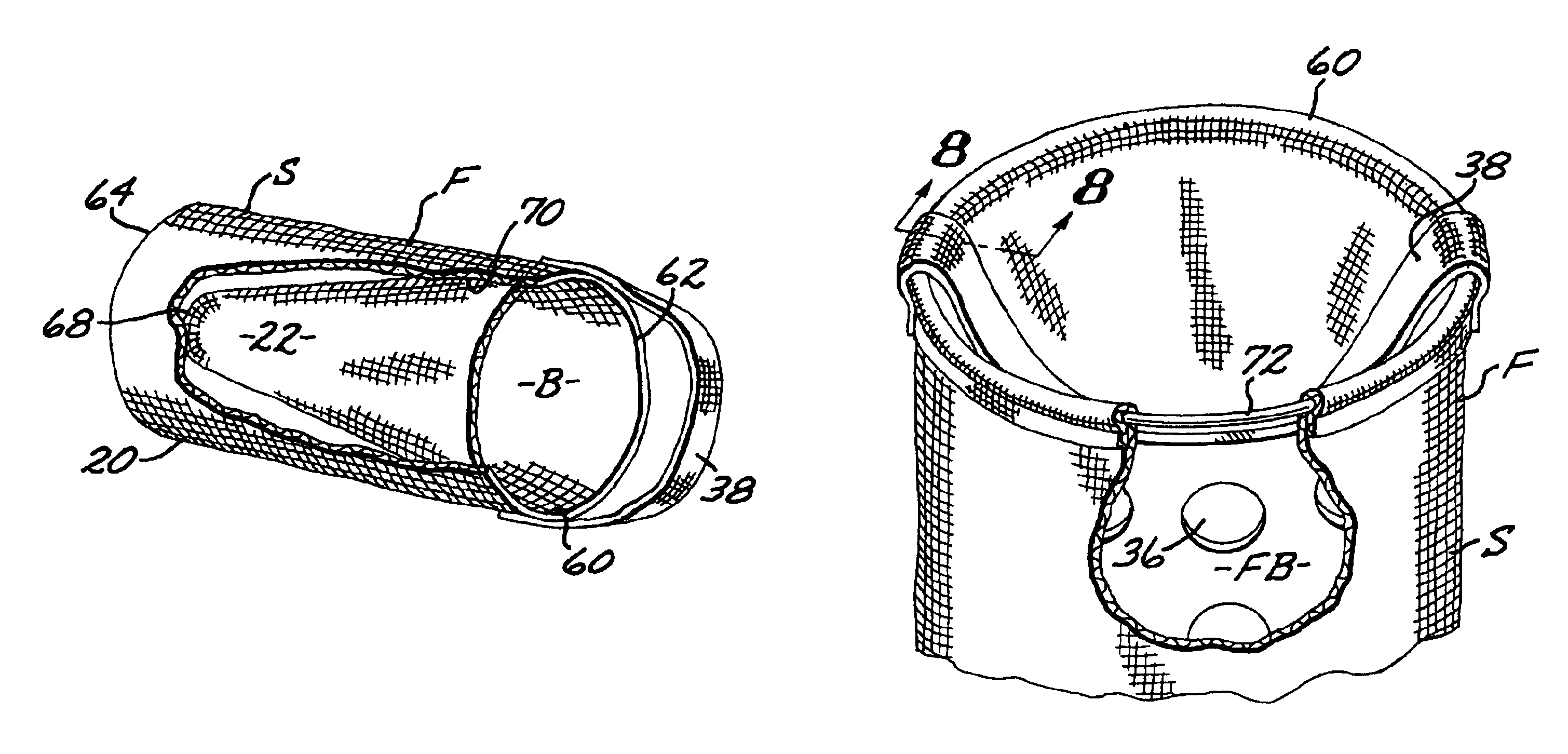
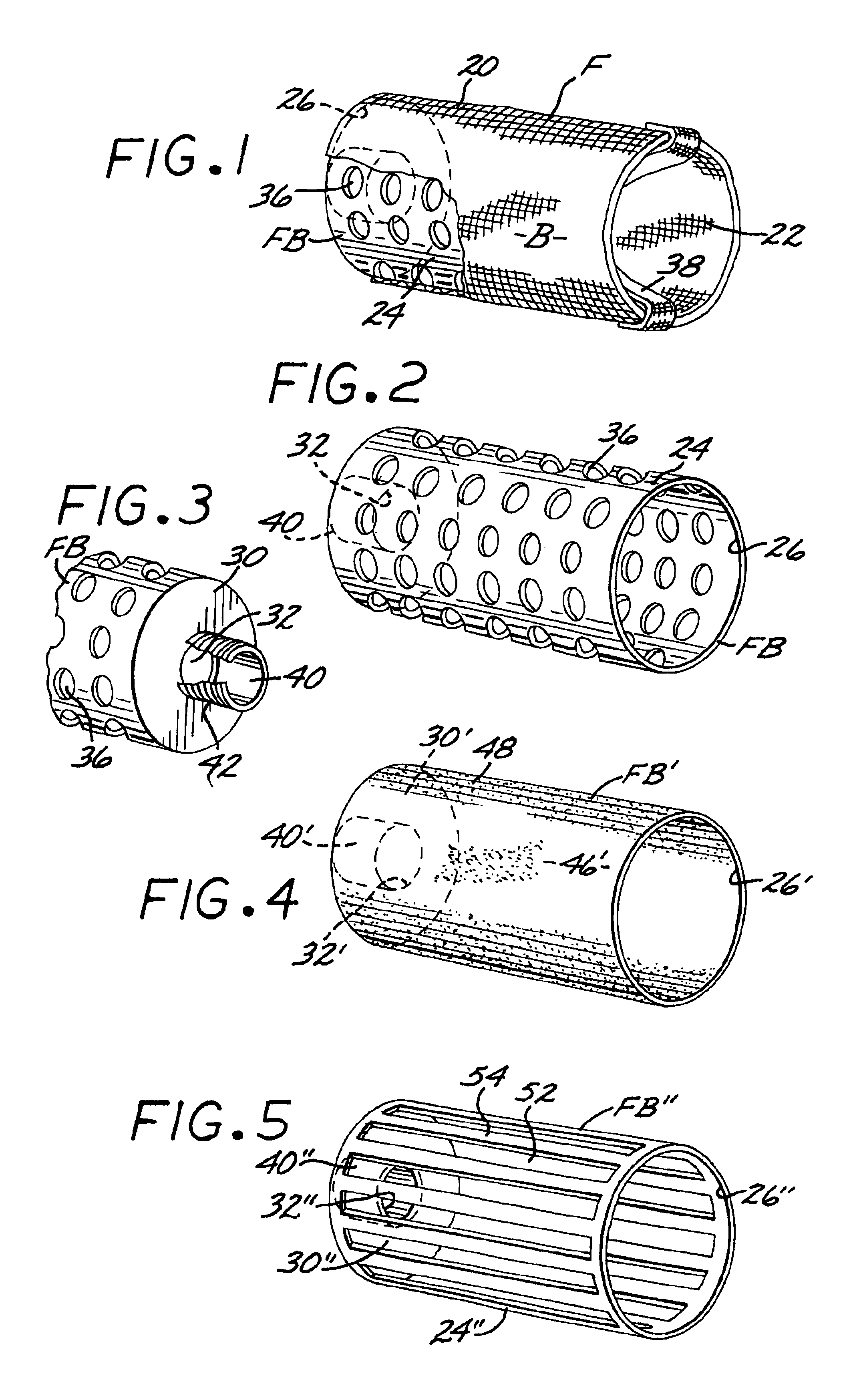
[0049]More particularly, referring to FIG. 1, a preferred embodiment of an internal spa filter F of the present invention includes a cylindrical filter body FB and a filter bag B having a cylindrical sheath 20 and a pocket 22 that extends concentrically inwardly from the inlet end of the sheath. The upper end of the cylinder 24 of the filter body is open t...


PUM

PropertyMeasurementUnit
weightaaaaaaaaaa
pore sizeaaaaaaaaaa
surface areaaaaaaaaaaa

Abstract

A filter for a spa or pool, having a filter body which receives a filter bag having a sheath encompassing the exterior of the filter body and a pocket extending inwardly from the front end of the sheath into the filter. Operation of the spa water circulation system draws spa water into the filter bag pocket while concurrently spa water is drawn transversely through the filter bag sheath and auxiliary spa water openings into the filter body. An O-ring encircles the upper portion of the filter bag to releasably retain such bag to the filter body during operation of the spa water circulation system.

Description

CROSS-REFERENCE TO RELATED APPLICATION[0001]This application is a divisional of U.S. patent application Ser. No. 10 / 448,876 filed by me on May 30, 2003, which is a continuation in part of U.S. patent application Ser. No. 09 / 990,616, filed by me on Nov. 21, 2001, now U.S. Pat. No. 6,685,843.BACKGROUND OF THE INVENTION[0002]1. Field of the Invention[0003]The present invention relates to filters for liquids. More particularly, the present invention is directed to an internal filter for use in the water circulation systems of conventional pools or spas.[0004]2. Description of Related Art[0005]Filters of various configurations are known in the art for use in swimming pools, spas, and the like in order to remove solid particles and debris from the circulated water. Such filters are typically mounted in-line within the pool or spa circulation system and are configured with a liquid-permeable filter media such that, when the circulation system is in operation, the water can be pulled throug...

Claims


Application Information

Patent Timeline
Patent Type & Authority Patents(United States)
IPC IPC(8): B01D29/27B01D29/13C02F1/00
CPCB01D29/27C02F1/004B01D2201/0415C02F1/001C02F2103/026C02F2103/42Y10S55/02Y10S55/26C02F2201/006E04H4/1272C02F1/00
Inventor LEAVERTON, GREGG W.
Owner ORIX CAPITAL MARKETS LLC
Why Eureka
Try Eureka