
Method for performing statistical post processing in semiconductor manufacturing using ID cells

Inactive Publication Date: 2005-09-06
BELL SEMICON LLC
View PDF4 Cites 52 Cited by
  • Summary
  • Abstract
  • Description
  • Claims
  • Application Information

AI Technical Summary

Benefits of technology

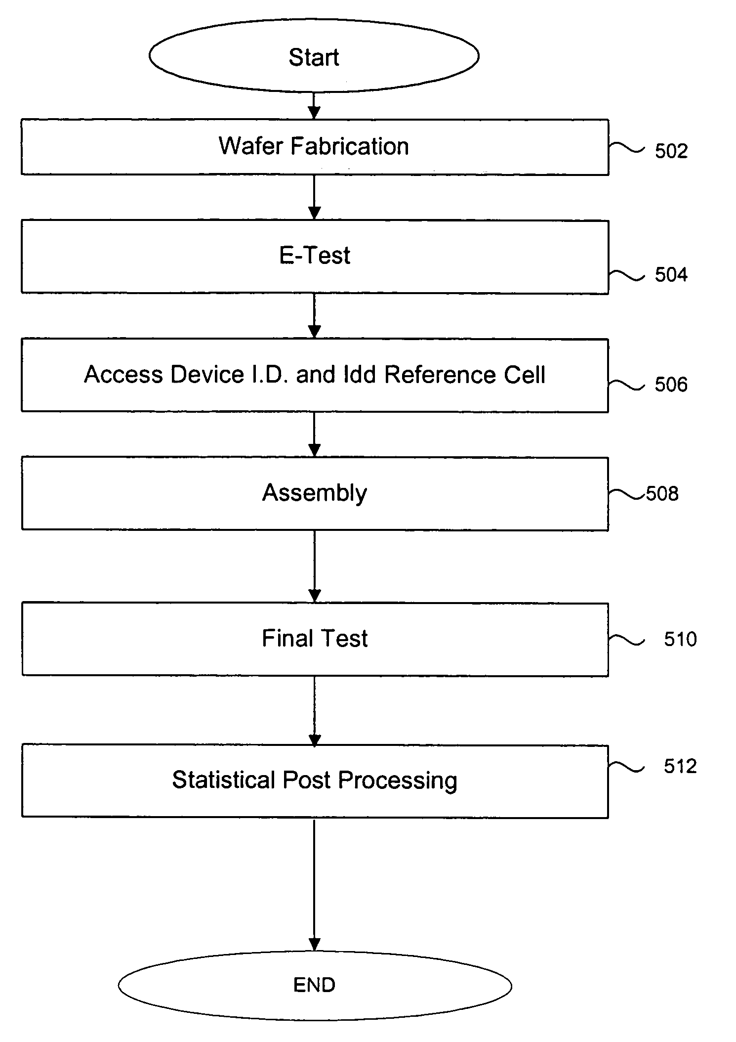
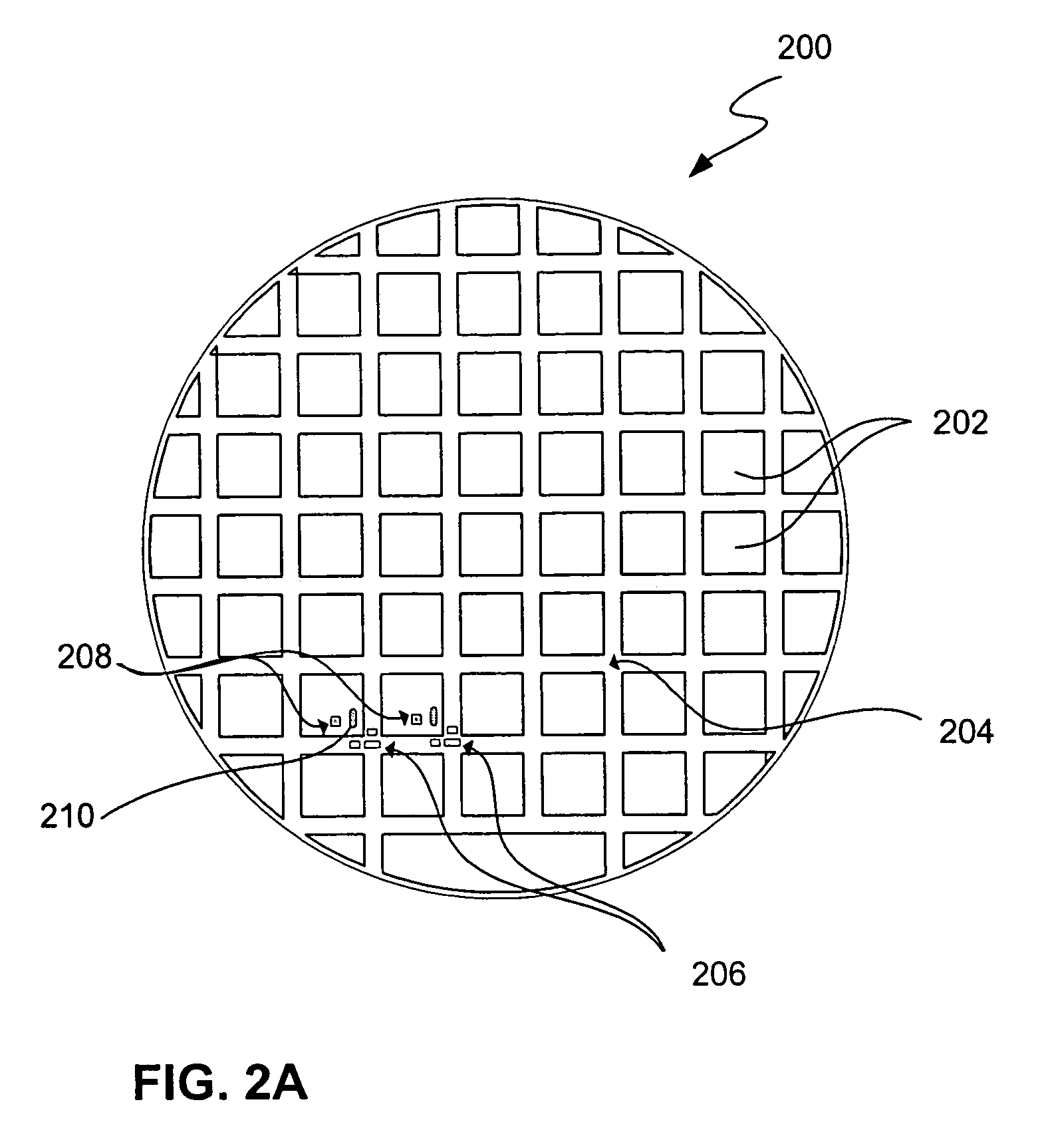
[0017]The time and expense of customized wafer probe cards is avoided in one embodiment by providing a generic test interface, such as a variation of an electrical testing structure (i.e., e-test) probe card, the test fixture interface configured to provide electrical contact with pads and other contacts on the wafer. Data such as an identification number for the device can be thus monitored at the same time that the e-test structures located in the scribe streets are accessed. Further, an electrical parameter for the integrated circuit die, such as a supply current from a reference test cell located within the integrated circuit can also be monitored using the generic interface. Using this wafer level data, and optionally data obtained after the die si separated form the wafer, statistical post processing can be performed to identify wafer defect patterns.

Problems solved by technology

As integrated circuit devices grow smaller and smaller, the testing of the integrated circuits presents greater challenges.
For example, the shrinkage of transistor sizes to the point that critical dimensions are well below one micron (10−6 m), has resulted in more elaborate and expensive testing fixtures to probe the contacts on the wafer during testing steps.
Many of these dies may have defects occurring during the fabrication process, for example during the patterning of layers, which affect the reliability of the die.
Some defects, for example, directly affect the functionality of the circuit resulting in functional failure.
Other defects may adversely affect the reliability of the circuit resulting in an early lifetime failure or failure under varying operating conditions.
Unfortunately, the wafer probe operation is a very delicate and time consuming operation requiring a great deal of skill.
Since probe cards must be custom built for each new integrated circuit design to match the particular metallic pad configuration for that design, expenditures for probe cards can be substantial.
Unfortunately, the production run of the dies may be of a small volume, and thus building test fixtures (such as probe cards) that are specific to the design may not be economically justified.
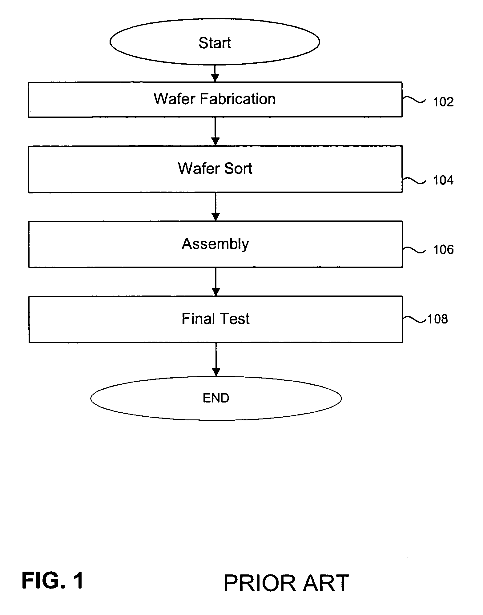
Unfortunately, skipping the wafer sort step results in the loss of information regarding the original location of the die a particular wafer.
A rogue wafer might yield very poorly at the wafer probe step, i.e., falling far outside the specifications due to a process irregularity, and might result in a decision that the entire wafer represents a process excursion that should be completely contained and not shipped to the customer.
But if the wafer sort step was skipped, such information pertinent to all of the dies on the wafer would not otherwise be available at the final test step.
That is, a slightly depressed yield at final test will not provide sufficient information to determine that all units built from a given wafer should be rejected, even if individual package die could be correlated to a particular wafer.

Method used


Image

  • Method for performing statistical post processing in semiconductor manufacturing using ID cells
  • Method for performing statistical post processing in semiconductor manufacturing using ID cells
  • Method for performing statistical post processing in semiconductor manufacturing using ID cells

Examples


Embodiment Construction

[0030]Reference will now be made in detail to preferred embodiments of the invention. Examples of the preferred embodiments are illustrated in the accompanying drawings. While the invention will be described in conjunction with these preferred embodiments, it will be understood that it is not intended to limit the invention to such preferred embodiments. On the contrary, it is intended to cover alternatives, modifications, and equivalents as may be included within the spirit and scope of the invention as defined by the appended claims. In the following description, numerous specific details are set forth in order to provide a thorough understanding of the present invention. The present invention may be practiced without some or all of these specific details. In other instances, well known process operations have not been described in detail in order not to unnecessarily obscure the present invention.

[0031]In a preferred embodiment of the invention, a method of manufacturing a semico...


PUM


Abstract

A method of manufacturing a semiconductor integrated circuit includes providing a fabricated integrated circuit on a wafer. A test fixture is connected to unencapsulated pads on the integrated circuit to monitor an operating parameter for the circuit and to determine a unique identifier for the die. The parameter is analyzed in post processing.

Description

BACKGROUND OF THE INVENTION[0001]1. Field of the Invention[0002]The present invention relates to processes involved in the manufacturing of semiconductor devices. More particularly, the present invention relates to methods for testing integrated circuits.[0003]2. Description of the Related Art[0004]As integrated circuit devices grow smaller and smaller, the testing of the integrated circuits presents greater challenges. For example, the shrinkage of transistor sizes to the point that critical dimensions are well below one micron (10−6 m), has resulted in more elaborate and expensive testing fixtures to probe the contacts on the wafer during testing steps.[0005]Semiconductor wafer fabrication involves a series of processes used to create semiconductor devices and integrated circuits (IC's) in and on a semiconductor wafer surface. Fabrication typically involves the basic operations of layering and patterning, together with others such as doping, and heat treatments. Typically, a large...

Claims


Application Information

Patent Timeline
IPC IPC(8): H01L21/66H01L23/544
CPCH01L22/20H01L22/34H01L2223/5448
Inventor ALLEN, III, ERNESTCASTANEDA, DAVIDLOOI, MIAW
Owner BELL SEMICON LLC
Learn More