Capacitive sensor systems and methods with increased resolution and automatic calibration

a sensor and capacitive technology, applied in the field of capacitive sensing, can solve the problems of reliably detecting touch, metallic or other potentially dangerous components exposed on the outside of the toy or other object, and the limitations of pushbuttons or similar switches

Inactive Publication Date: 2005-09-06
IROBOT CORP
View PDF10 Cites 311 Cited by
  • Summary
  • Abstract
  • Description
  • Claims
  • Application Information

AI Technical Summary

Benefits of technology

[0022]The present invention provides and enables the foregoing features, benefits, and advantages, among others. In one aspect, the invention comprises low-cost methods and systems for capacitive proximity and contact sensing, using a simple sensor (which may be a conductive fiber or pattern of conductive ink) integrated with a microcontroller, with advanced digital signal processing that provides resolution enhancement, automatic and continuous calibration, noise reduction, and pattern recognition.
[0023]Basic Hardware Configuration: In one aspect, the capacitive sensing system includes a power source to supply electrical charge; a microcontroller, in communication with the power source and having at least one digital logic input / output (I / O) pin; a conductive sense element (which may be a plate, surface, wire, thread or conductive ink pattern) coupled to the port, and a resistance element coupled to the sense element. A variable capacitor configuration is formed by the sense plate and an object (such as a human hand) in proximity to the sense plate, and the capacitance thereof is representative of the proximity of the object to the sense element. After the conductive sense clement is charged by a voltage placed on the I / O pin, the time (or other parameter) necessary to discharge the sense element through the resistance element can be measured to determine the capacitance, and thus the proximity of an object to the sense element. By digitally processing the signals on the I / O pin, the system can provide resolution enhancement, automatic and continuous calibration, noise reduction and pattern recognition. In particular, the system can be made sensitive to very small changes of capacitance, despite large sensor offsets; relatively insensitive to random sensor noise caused, for example, by nearby electrical circuitry; self calibrating at the factory to compensate for variations in chip specifications and other manufacturing tolerances; and auto-calibrating to compensate for drift over time.
[0024]Measurement: In one aspect of the invention, capacitance is measured by measuring the time required to discharge the capacitance through a resistance using the above-described configuration of microcontroller I / O pin, sense element and resistor. In accordance with this aspect, a method includes: setting the I / O pin to OUTPUT mode with its state HIGH, thus charging the capacitor to the supply voltage of the microcontroller; then setting the I / O pin to INPUT mode (referred to hereinafter as changing the direction of the I / O pin or turning around the I / O pin); and then measuring the time required for the voltage measured at the pin (V.pin) to fall below the threshold voltage of the microcontroller. The measured discharge time is approximately proportional to the resistance of the resistor (R.discharge) times total capacitance (C). Since the microcontroller uses a stable clock, digital signal processing techniques are employed to make high-resolution measurements of time. In this way, small changes in capacitance (C) can be reliably measured.
[0033]A pet sensor detects a petting contact and distinguishes it from other types of touch (and from noise), using techniques similar to the rhythm sensor, but also including a bandpass filter to preprocess the signal before the detection of rising and falling edges. In this preprocessing, the raw capacitive sensor values are passed first to a low-pass filter. The output of the low-pass filter is then filtered again through a high-pass filter. In applications that can afford the use of a small amount of extra memory for the filtering operations, this results in significantly better performance in distinguishing a true petting motion from other kinds of touch and spurious noise.
[0038]The invention provides numerous technical advantages. For example, the sensor utilizes existing I / O and stable clock source of standard, low-cost microcontrollers already present in many “smart” objects; and since the system uses only limited microcontroller resources (a sense element requires only a single I / O pin), one microcontroller can support many sensors (eight sensors can be operated from a typical 8-bit digital logic port). The hardware configuration of the invention requires only one external resistor per sensor, further reducing cost; and no variable frequency oscillator, frequency divider, or specific sense-plate geometries or materials are required. Integrated capacitive sensing and signal processing capabilities are thus provided with far fewer components and at lower cost than previously possible. The sensors are automatically and continuously calibrated, and integrated noise rejection reduces the incidence of false positives.
[0039]In practical applications, such as toys, the invention can reliably detect touch through several layers of fabric or stuffing or plastic; does not require metallic or other potentially dangerous components exposed on the outside; can be natural looking and feeling, thus enabling a more natural, non-mechanical interaction than that provided by conventional mechanical switches. Still further, the invention can detect not only touch, but also patterns of touch, such as tickle, pet, bounce, squeeze, burp, slap, or other. In a toy, this enables detection not only of whether a child is playing with the toy, but how the child is playing with the toy. The virtual sensor aspects of the system (e.g., a proximity sensor; a tickle sensor; a pet sensor) can compile and synthesize a wide range of information from one or more simple physical sensors (such as a pattern of conductive ink); and enable recognition and “learning” of signal patterns or signatures. This enables a powerful interactivity capability, since the toy or other object “knows” how it is being manipulated (squeeze, tickle, pet, slap, or other) and can even “learn” the interactivity patterns of its user(s).

Problems solved by technology

However, pushbuttons or similar switches suffer from a variety of limitations.
In addition, many sensing systems typical of the prior art cannot reliably detect touch through several layers of fabric or stuffing or plastics, and leave metallic or other potentially dangerous components exposed on the outside of the toy or other object.
Still further, existing switching systems add complexity, cost and reliability problems.
From a practical standpoint, however, while capacitive sensing is well-known, the components required by prior art methods and systems have generally been too expensive and complex for deployment in toys and other low-cost objects.

Method used


Image

  • Capacitive sensor systems and methods with increased resolution and automatic calibration
  • Capacitive sensor systems and methods with increased resolution and automatic calibration
  • Capacitive sensor systems and methods with increased resolution and automatic calibration

Examples


Embodiment Construction

provides additional information and further examples.

BRIEF DESCRIPTION OF THE DRAWINGS

[0041]The invention, as well as features and advantages thereof, will be more readily understood from a reading of the following detailed description of various examples thereof, and by reference to the accompanying drawings, wherein:

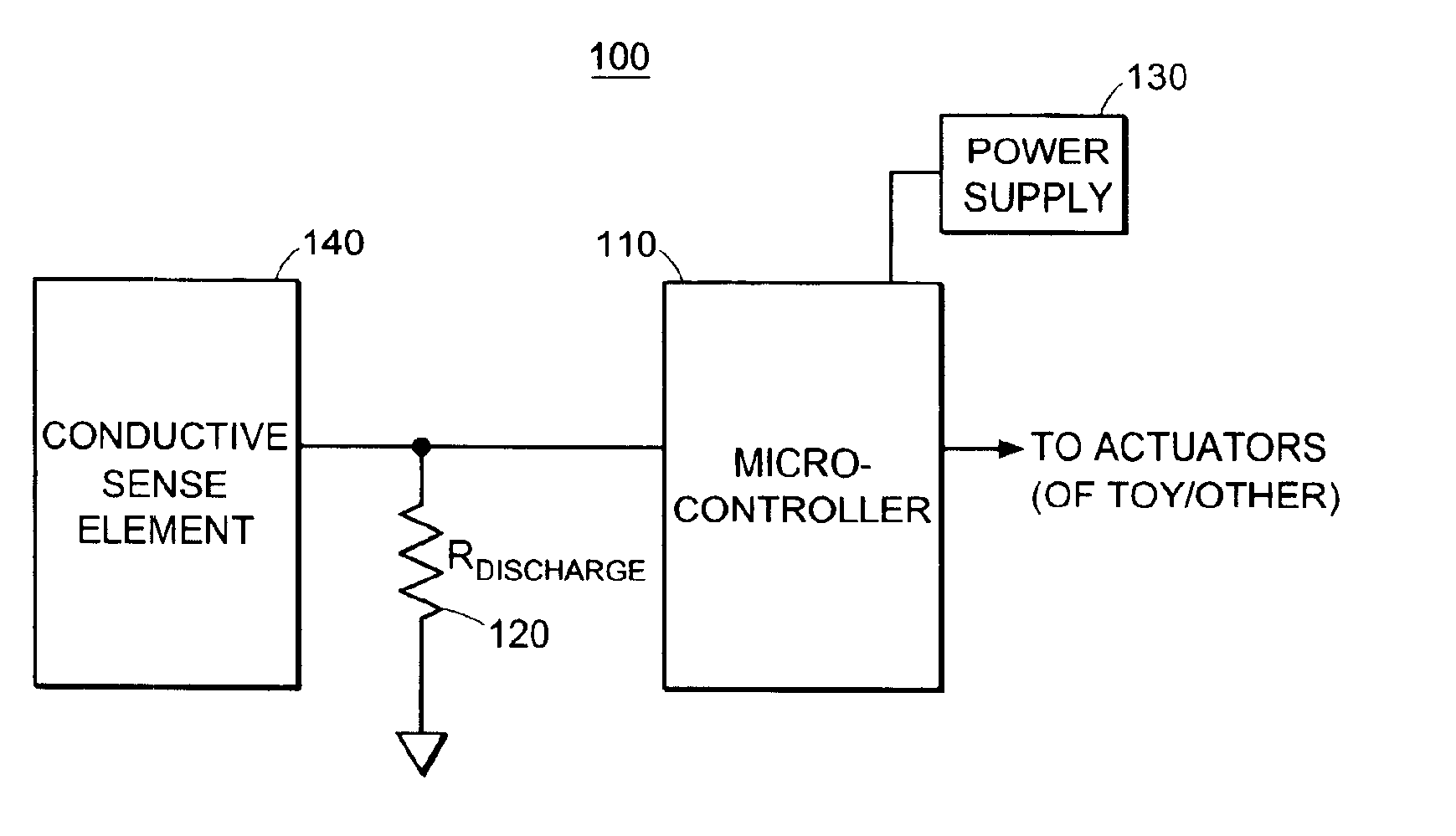
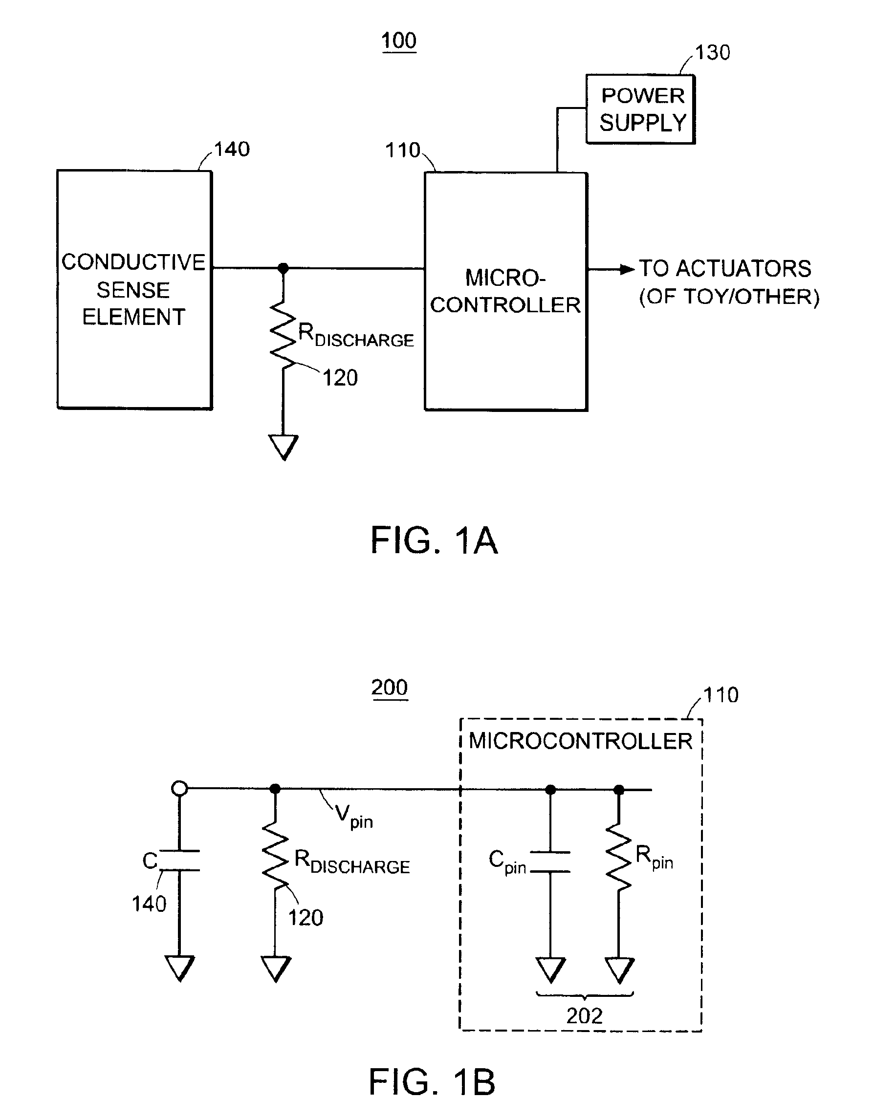
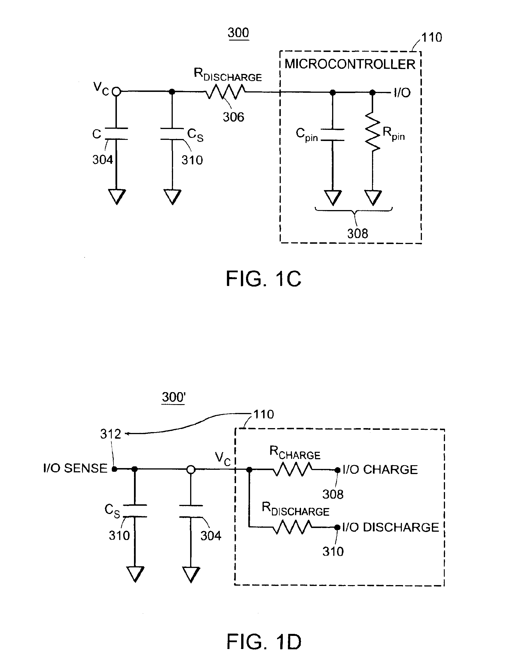
[0042]FIGS. 1A-1F are a schematic drawing showing electrical circuitry employed in embodiments of the present invention;

[0043]FIGS. 2A-2D are flowcharts of method steps utilized in conjunction with the invention;

[0044]FIG. 3 is a schematic diagram illustrating virtual sensor processes within the microcontroller; and

[0045]FIG. 4 is a schematic diagram illustrating an embodiment of the invention that provides non-contact object identification.

DETAILED DESCRIPTION

[0046]The following description and accompanying drawings describe and illustrate various embodiments of the methods and systems of the present invention. It will be understood that while several examples shown a...


PUM


Abstract

Methods and systems for capacitive proximity and contact sensing employ one or more simple sensors (which may be a conductive fiber or pattern of conductive ink) in communication with a microcontroller. Digital signal processing executed by the microcontroller enables resolution enhancement, automatic and continuous calibration, noise reduction, pattern recognition and the configuration of virtual sensors capable of detecting how an object incorporating the sensors is being manipulated.

Description

CROSS-REFERENCE TO RELATED APPLICATIONS[0001]The present application for United States Patent is a Rule 53(b) nonprovisional continuation patent application based upon, and claims the priority of, U.S. nonprovisional patent application Ser. No. 10 / 038,111, filed 02 Jan. 2002, now U.S. Pat. No. 6,661,239 entitled Capacitive Sensor Systems and Methods with Increased Resolution and Automatic Calibration and the following U.S. Provisional Applications for Patent assigned to iRobot Corporation of Somerville, Mass., the assignee of the present application:[0002]Ser. No. 60 / 259,360, filed Jan. 2, 2001, entitled “Toy Sensors”; and[0003]Ser. No. 60 / 266,260, filed Feb. 2, 2001, entitled “Capacitive Sensor”.[0004]Each of these applications is incorporated by reference herein as if set forth in its entirety.FIELD OF THE INVENTION[0005]The present invention relates in general to the field of capacitive sensing, and in particular, to capacitive sensing methods and systems having increased resolut...

Claims


Application Information

Patent Timeline
Patent Type & Authority Patents(United States)
IPC IPC(8): G01D5/24G01D5/12G01D18/00
CPCG01D5/2405G01D18/006G01D18/008H03K17/962H03K2217/94026
Inventor OZICK, DANIEL N.
Owner IROBOT CORP
Why Eureka
Try Eureka