
Oscillator circuit

a technology of oscillator circuit and oscillator, which is applied in the direction of oscillation generator, modulation, pulse technique, etc., can solve the problems of phase noise increase, and achieve the effect of reducing errors and facilitating generation

Inactive Publication Date: 2008-05-13
INFINEON TECH AG
View PDF8 Cites 2 Cited by
  • Summary
  • Abstract
  • Description
  • Claims
  • Application Information

AI Technical Summary

Benefits of technology

This configuration reduces the impact of component variations and allows for precise frequency adjustment with reduced phase noise, enabling larger component sizes and more stable frequency settings.

Problems solved by technology

The intense nonlinear response of the frequency-voltage characteristics of CMOS components and particularly of CMOS varactor diodes means that particular challenges are placed on the implementation of frequency adjustment for voltage controlled oscillators in CMOS technology.
In addition, the phase noise increases as the fundamental frequency of an output signal from a voltage controlled oscillator implemented in this manner rises.

Method used


Image

  • Oscillator circuit
  • Oscillator circuit
  • Oscillator circuit

Examples


Embodiment Construction

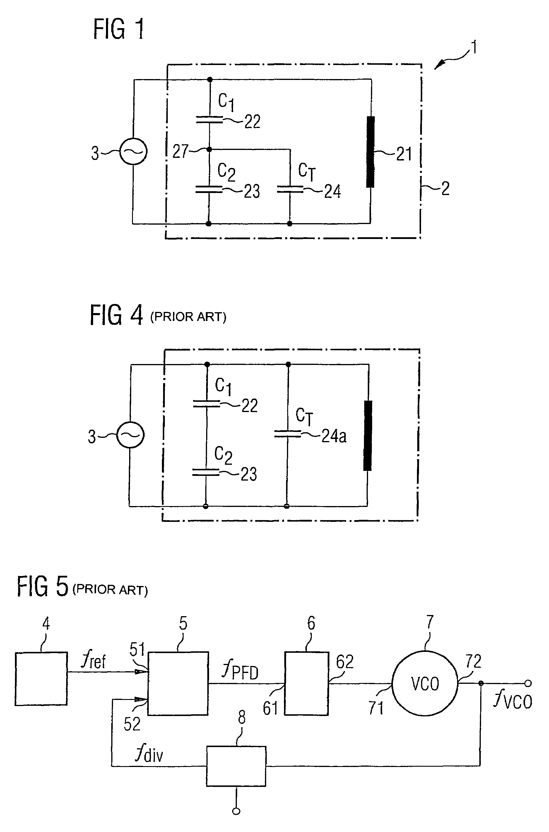
[0028]Generally, the following applies for the resonant frequency of a resonant circuit:

[0029]f=12⁢π⁢LC

[0030]The resonant frequency f for a resonant circuit is proportional to the reciprocal of the square root of the product of the inductive element L and of the capacitive element C.

[0031]To set the resonant frequency of a resonant circuit as appropriate, a further capacitive element is expediently introduced, whose capacitance value is adjustable. This allows the resonant frequency of the resonant circuit to be changed.

[0032]FIG. 4 shows a block diagram of a prior art oscillator containing such a resonant circuit. In this context, the term “oscillator” is intended to be understood to mean circuits which generate undamped electrical oscillations of particular curve shape and frequency at substantially constant amplitude. In this case, the frequency is determined by the resonant frequency f of the resonant circuit. Since resonant circuits have damping, it is necessary to provide an a...


PUM


Abstract

The invention is directed to an oscillator circuit in which a frequency-determining resonant circuit includes an inductive element, a first capacitive element and at least one second capacitive element which is connected in series with the first capacitive element. A node is provided between the first capacitive element and at least one second capacitive element. The oscillator circuit contains a damping reduction amplifier which is arranged in parallel with the frequency-determining resonant circuit. In addition, the oscillator circuit has a first tuneable capacitive element, which is connected in parallel with the first capacitive element of the resonant circuit and has a connection connected to the node.

Description

REFERENCE TO RELATED APPLICATIONS[0001]This application claims the benefit of the priority date of German application DE 10 2005 003 904.9, filed on Jan. 27, 2005, the contents of which are herein incorporated by reference in their entirety.FIELD OF THE INVENTION[0002]The invention relates to an oscillator circuit.BACKGROUND OF THE INVENTION[0003]Oscillator circuits are generally used for providing a stable-frequency signal and are used, inter alia, in controlled oscillators which are part of a phase locked loop for mobile communication appliances.[0004]FIG. 5 shows a block diagram of such a phase locked loop which is used to generate signals at output frequencies of up to several gigahertz. The phase locked loop shown comprises a voltage controlled oscillator 7 having an actuating input 71 and a signal output 72, at which the output signal at the frequency fVCO can be tapped off. The signal which is output by the voltage controlled oscillator 7 is supplied to a feedback path which ...

Claims


Application Information

Patent Timeline
Patent Type & Authority Patents(United States)
IPC IPC(8): H03B5/12
CPCH03B5/1228H03B5/1215H03B5/1253
Inventor PITTORINO, TINDARO
Owner INFINEON TECH AG
Learn More