Eureka AIR delivers breakthrough ideas for toughest innovation challenges, trusted by R&D personnel around the world.

Antenna arrangement

Inactive Publication Date: 2005-09-06
KATHEIN WERKE KG
View PDF20 Cites 23 Cited by
  • Summary
  • Abstract
  • Description
  • Claims
  • Application Information

AI Technical Summary

Benefits of technology

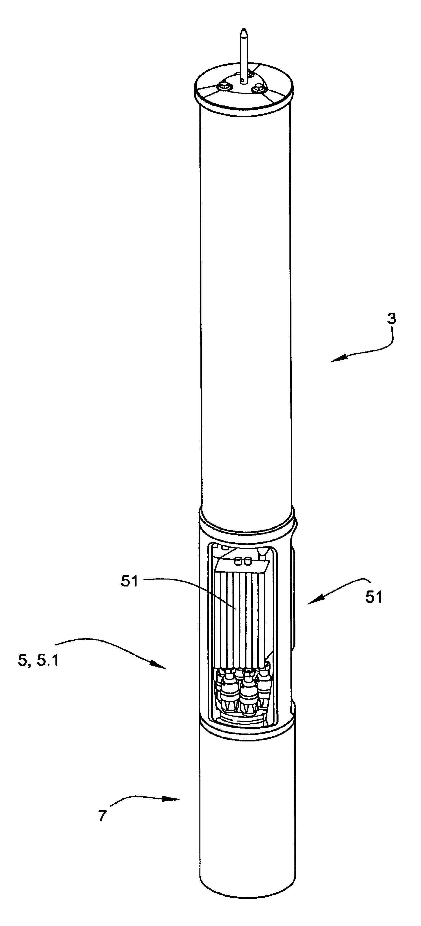
[0011]In fact, it must be regarded as surprising that the exemplary illustrative non-limiting implementations results in a very highly robust antenna arrangement which is in the form of a pylon, with all of the antenna systems being concealed in a tubular radome which can be designed to be extremely thin. This radome can preferably—as with other known systems as well—have a cylindrical cross section, but may also have any other desired horizontal cross section, for example being polygonal with n sides, or being oval etc. Furthermore, the exemplary illustrative non-limiting antenna arrangement is distinguished by having a service zone in which all the relevant adjustment and connection measures can be carried out, without having to dismantle the entire antenna pylon or else having to remove just the entire radome in advance in order to gain access to the components located underneath it.
[0016]The exemplary illustrative non-limiting antenna arrangement and the compact construction furthermore for the first time make it possible to construct an antenna device such as this effectively as an omnidirectional antenna by means of appropriate interconnection in the service zone. In this case, the antenna elements can preferably be adjusted to have a different transmission angle with respect to the horizontal plane, by means of a down-tilt device which can be controlled remotely.
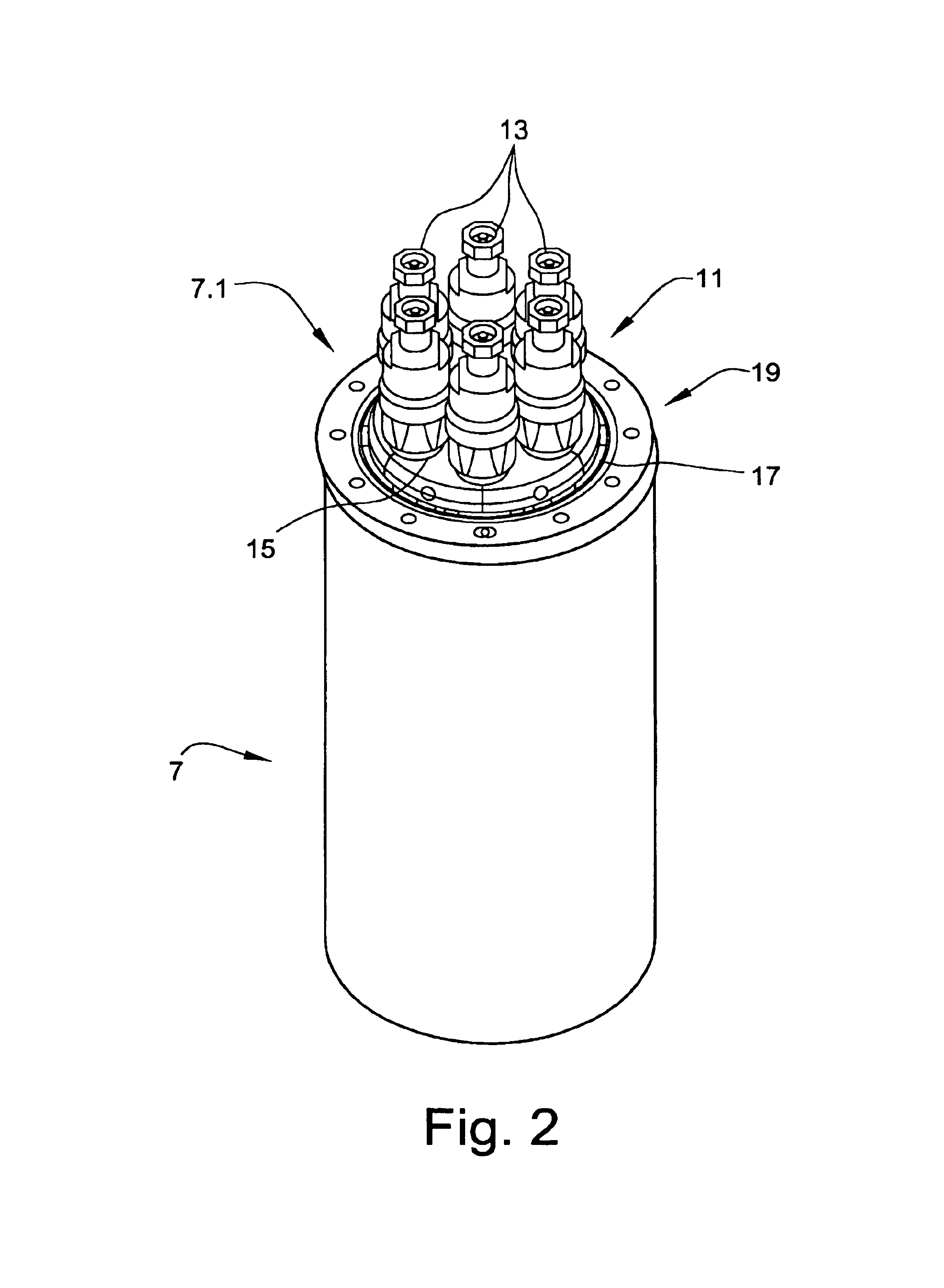
[0018]The service zone is constructed such that it can be mounted on the blunt head of a pylon, at which the necessary antenna cables which lead to the antenna device end at an interface which is formed in this way. This blunt pylon is to this extent also referred to in the following text as the pylon foot, pylon base or else as the antenna foot or antenna base. When the service zone is open, the appropriate intermediate cables can be installed, thus producing an electrical connection from the cables which end in the antenna foot to the connecting points, which are provided in the upper area of the service zone, for the cables which lead to the antenna elements. Any desired necessary components such as amplifiers etc. can likewise be accommodated in these service zones. The amplifiers may, for example, be what are referred to as TMAs, TMBs etc. Some of the amplifiers or other circuits which also, for example, develop heat which must be dissipated to the outside can be designed and arranged such that a portion of the amplifier housing is at the same time used as a covering cap closing arrangement for the opening in the service zone, so that these devices can optimally emit the heat produced by them to the outside (some of the devices which produce heat thus represent a portion of the outer casing of the antenna arrangement). Since these amplifiers are now located closer to the actual antenna elements (and no longer in a separate base station), not only does this reduce the number of cables which need to be laid from the base station to the antenna elements, but the power which is required for the amplifiers in the antenna arrangement can also be reduced, for example by a factor of 2. Finally, it is possible to reduce not only the number of electrical cables and glass fiber cables which are used but also, possibly, to reduce the diametric cross section that they need to have. The down-tilt adjusting devices which can be remotely controlled, for example motor units which can be driven approximately, can also be accommodated, for example, in the service zone and then drive the plastic shifters (which are located within the radome) in order to set the different down-tilt angles, for example via a transmission linkage.
[0020]The service zone can preferably be fixed and detached via bolt connections such that, even in a state when it is secured by the bolt connection, the service zone, and hence the pylon structure which is located above it, can carry out an axial rotary movement. This allows the antenna elements to be aligned appropriately.

Problems solved by technology

The overall physical complexity, including installation on site, but in particular the difficulty in carrying out repairs have been found to be major disadvantages with the last-mentioned antenna systems.
Particularly when, for example, components are not just to be replaced but are also intended to be fitted retrospectively, this involves considerable installation effort in order first of all to remove all of the cladding, to retrofit the appropriate components at a high altitude, in order then to fit the cladding once again once the work has been carried out.
Another major disadvantage which has been found with the prior art of the generic type, as well, is that, at certain relatively high wind speeds, the entire antenna pylon can resonate in such a way that the radome is fractured.
Furthermore, the exemplary illustrative non-limiting antenna arrangement has a damping device which ensures that the antenna structure, and in particular the radome, cannot resonate at an appropriate wind speed, thus destroying the system or parts of it.

Method used


Image

  • Antenna arrangement
  • Antenna arrangement
  • Antenna arrangement

Examples


Embodiment Construction

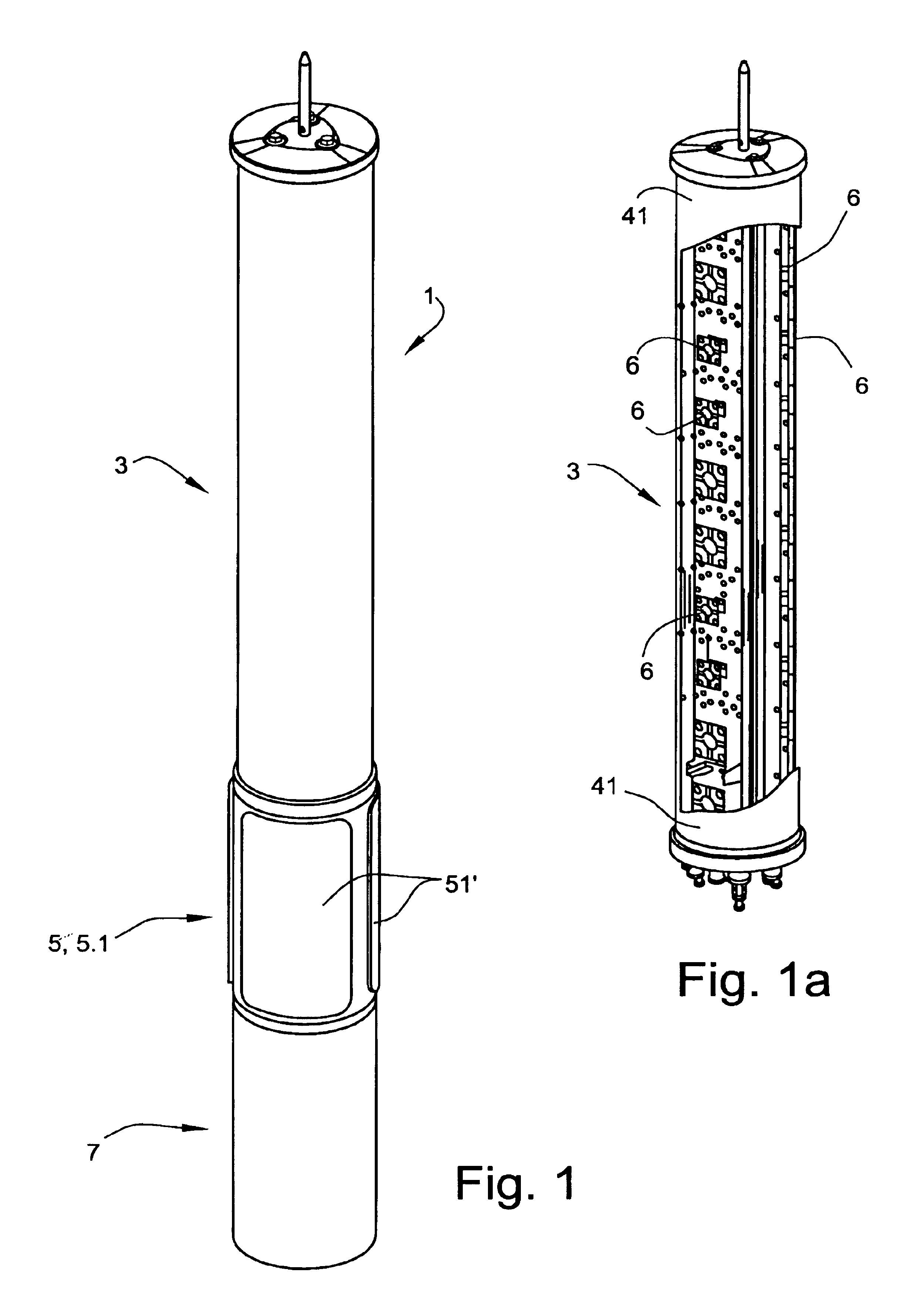
[0038]FIG. 1 shows an exemplary illustrative non-limiting schematic perspective illustration of an antenna arrangement 1 as may be used in particular as a mobile radio antenna for a base station.

[0039]The antenna arrangement 1 has an antenna section 3 which is located at the top, and at least one further antenna section 5 which is located underneath it and has at least one service zone 5.1.

[0040]The entire arrangement comprising the upper antenna section 3 and the lower antenna section 5 which is axially adjacent to it is constructed and mounted on an antenna stand device 7, which is used as an antenna base 7. This antenna base 7 need not necessarily be in the form of a pylon as shown in FIG. 1 et seq, but may also have a large or smaller diameter or a different cross-sectional shape, or may, for example, also be in the form of a connecting point at ground level, on which the antenna arrangement 1 is then mounted with the at least upper antenna section 3 and the at least one lower a...


PUM


Abstract

An improved antenna arrangement is subdivided at least into an upper antenna section and at least one lower antenna section. The upper section has a mounting core, the antenna elements and a radome. At least one lower antenna section is axially adjacent underneath the upper section. The lower antenna section is equipped as a service zone which has at least one access opening, which runs in the circumferential direction, to the internal area in the service zone. The radome is held and anchored elastically via at least two damping arrangements, which are offset with respect to one another in the axial direction, and / or via damping device, which are offset with respect to one another.

Description

FIELD[0001]The technology herein relates to an antenna arrangement.BACKGROUND AND SUMMARY[0002]By way of example, an article with the title “Neue Sendeantenne auf dem Säntis, Schweitz” [New transmitting antenna at S{hacek over (a)}ntis, Switzerland] was published in the magazine for customers of the company Kathrein-Werke KG (December 1997 issue). This article indicates that the transmitting systems comprise transmitting antennas for broadcast radio, television and mobile radio. The high attitude and, associated with this, the extremely low temperatures in winter made it necessary to use a double-walled radome which can be heated, and within which the antenna elements are accommodated.[0003]Comparable antenna devices have been disclosed, although these are generally intended for base stations for the field of mobile radio, so that the radome has a considerably smaller diameter than that in the prior art cited initially.[0004]Prior publications such as these have become known, for ex...

Claims


Application Information

Patent Timeline
IPC IPC(8): H01Q1/12H01Q1/24H01Q1/42
CPCH01Q1/246H01Q1/42
Inventor GOTTL, MAXIMILIANMUMMERT, WOLFGANGSTANISZEWSKI, WALTER
Owner KATHEIN WERKE KG
Why Eureka
Eureka Blog
Learn More