Tunable laser using microring resonator

a micro-ring resonator and laser technology, applied in the direction of laser details, laser optical resonator construction, optical resonator shape and construction, etc., can solve the problems of adverse effects on yield and pri

Inactive Publication Date: 2005-09-06
LAMBDA CROSSING
View PDF7 Cites 41 Cited by
  • Summary
  • Abstract
  • Description
  • Claims
  • Application Information

AI Technical Summary

Benefits of technology

[0006]The present invention relates to a monolithically integrated tunable laser, in which at least one microring resonator is used (replacing the superstructure gratings in the

Problems solved by technology

1. The spectral transmission of gratings consists of a single transmission peak. To generate the required sequence of spectral peaks, complex gratings have to be employed (variable period, segments of d

Method used


Image

  • Tunable laser using microring resonator
  • Tunable laser using microring resonator
  • Tunable laser using microring resonator

Examples


Embodiment Construction

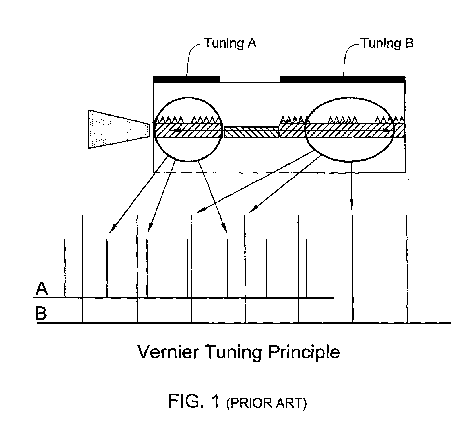
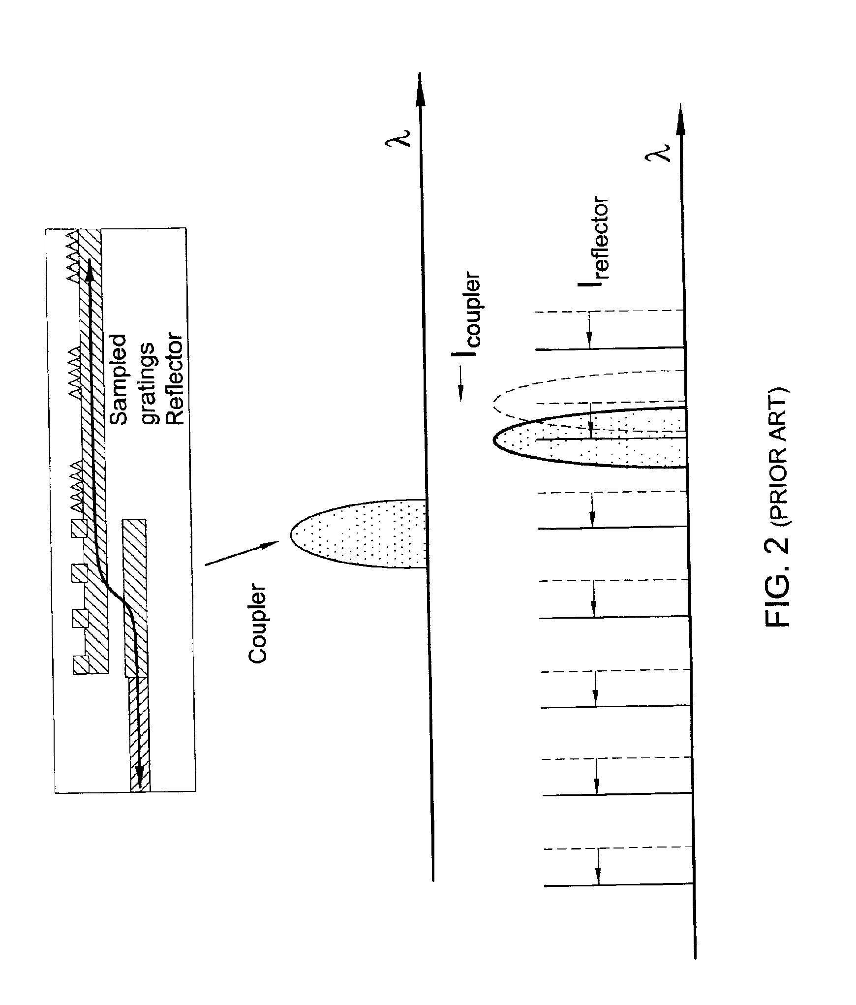
[0026]FIGS. 1 and 2 show prior art laser devices lasers of the kind utilizing the monolithical solution (based on a DBR). Laser structures according to the invention utilize microring resonators instead of at least superstructure or sampled gratings. The lasers can be fabricated by an epitaxial growth on InP, or other materials. In the non-limiting examples presented below, the InP based lasers that dominate the optical communications lasers are emphasized. The active laser layer and waveguide is referred to as 1.55 layers (the material composition made to emit light at 1.55 micrometer). Other waveguide layers are denoted as a 1.3 layer and a 1.14 layer, both transparent to the laser wavelength. They are deposited by a process of epitaxial regrowth over the processed wafer.

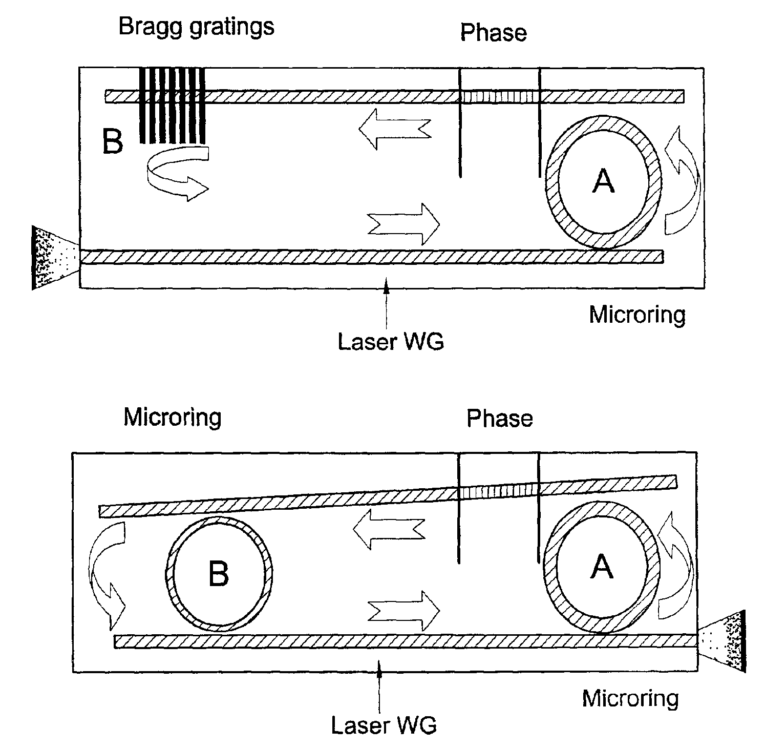
[0027]Referring to FIGS. 3A and 3B, a laser structure according to one embodiment of the present invention is schematically illustrated. This configuration is generally similar to the prior art SGDBR or SSGDBR str...


PUM


Abstract

A tunable semiconductor laser device is presented. The device comprises a laser structure formed by at least two waveguides and an active region located within at least a segment of one of the waveguides; and comprises a tunable spectral filter optically coupled to the laser structure. The tunable spectral filter includes at least two filtering elements, at least one of them being a microring cavity.

Description

FIELD OF THE INVENTION[0001]This invention is generally in the field of optical devices and relates to a tunable laser using a microring resonator.BACKGROUND OF THE INVENTION[0002]Widely tunable semiconductor lasers are important elements for next generation optical communications systems and possibly for other applications such as testing, biomedical, inspection, etc.[0003]Current methods embedded in widely tunable semiconductor lasers are generally divided into: (1) externally tuned lasers (external cavity laser—ECL) and lasers utilizing a monolithical solution based on a distributed Bragg reflector laser (DBR)—see Table 1. In the ECL, the laser cavity is comprised of a semiconductor chip and external spectrally sensitive elements (mainly gratings) that serve as an out of chip wavelength selective mirror. Tuning of the laser is performed by rotating or modifying the external gratings (by applying an external field such as heat, stress, etc.). This type of tunable laser is problema...

Claims


Application Information

Patent Timeline
IPC IPC(8): H01S3/10H01S5/0625H01S5/12
CPCH01S5/06255H01S5/1032H01S5/1071H01S5/12
Inventor ORENSTEIN, MEIRMARGALIT, MOTI
Owner LAMBDA CROSSING
Why Eureka
Try Eureka