Bidirectionally transmittable optical wavelength division multiplexed transmission system

Inactive Publication Date: 2005-09-06
FUJITSU LTD
View PDF11 Cites 42 Cited by
  • Summary
  • Abstract
  • Description
  • Claims
  • Application Information

AI Technical Summary

Benefits of technology

[0014]According to the invention, the optical wavelength division multiplexed transmission system that transmits optical signals bidirection

Problems solved by technology

However, to use distributed amplifiers in two-way communications, the following problem must be considered.
Of these two amplifying techniques, forward pumping is known to cause interference between the optical signal and the pumping light since the optical signal and the pumping light travel in the same direction, and this degrades transmission quality, as discussed in the paper prepared by Yasuhiro Aoki, Shunji Kishida, and Kunihiko Washio (“Stable cw backward Raman amplification in optical fibers by stimulated Brillouin scatt

Method used


Image

  • Bidirectionally transmittable optical wavelength division multiplexed transmission system
  • Bidirectionally transmittable optical wavelength division multiplexed transmission system
  • Bidirectionally transmittable optical wavelength division multiplexed transmission system

Examples


first embodiment

[0028]FIG. 3 is a diagram illustrating the invention.

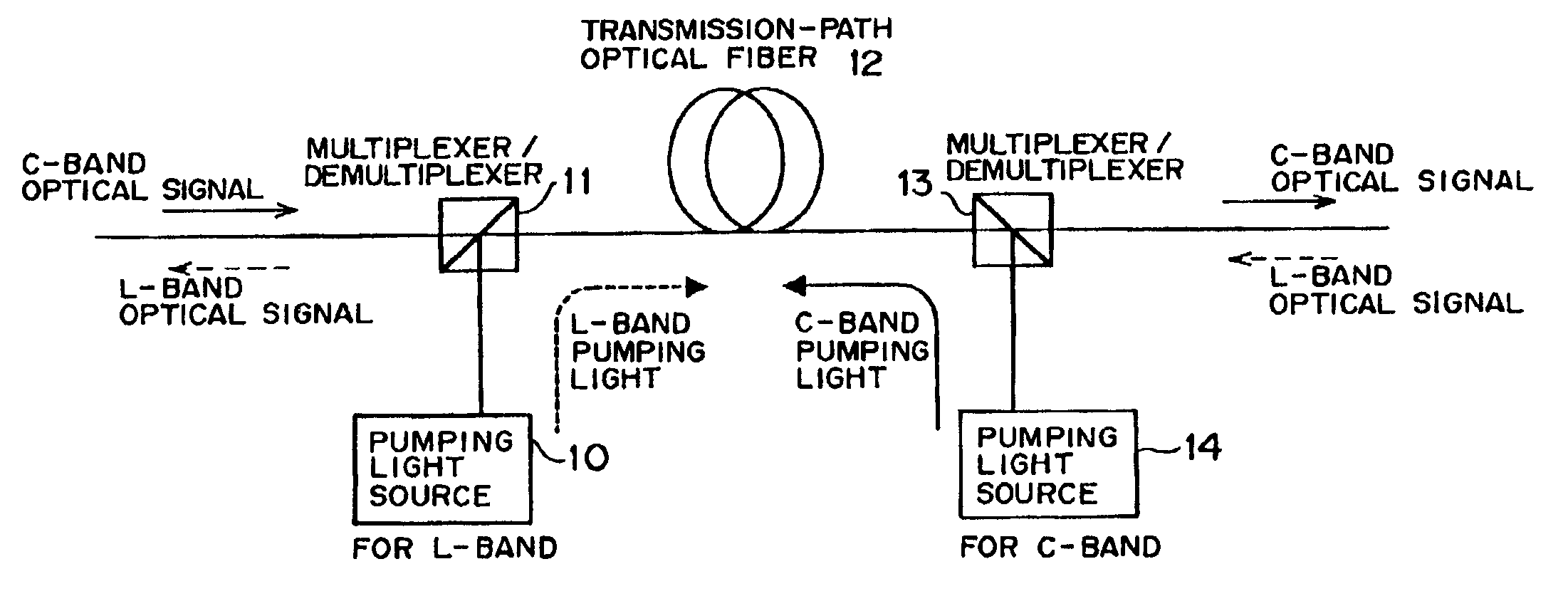
[0029]Wavelength bands used are a C-band and an L-band, to which upstream and downstream paths are allotted, respectively. It is supposed that the C-band has a band of wavelengths ranging from 1529.55 nm to 1563.86 nm, and that the L band has a band of wavelengths ranging from 1567.95 nm to 1604.03 nm. Further, the wavelength of pumping light for distributed amplification of the C-band is in the 1435-1445 nm range, and the same wavelength for distributed amplification of the L-band is in the 1475-1485 nm range.

[0030]Although L-band pumping light is combined with the C-band optical signal in a transmission-path optical fiber codirectionally with the C-band signal (in the upstream direction), the C-band signal is not affected by the L-band pumping light, because the C-band signal contains wavelengths for pumping which are different from the wavelength of the L-band pumping light, and hence amplified only through backward pumping imp...

third embodiment

[0041]FIG. 5 is a diagram showing the invention.

[0042]It is assumed in FIG. 5 that a C-band optical signal is transmitted in the direction of the solid arrow and that an L-band optical signal is transmitted in the direction of the dotted arrow. Let the C-band be taken as an example. A C-band optical signal from a C-band transmitter is separated from an L-band optical signal by a WDM coupler 20 (or a wavelength-selective multiplexer / demultiplexer), and then amplified by a C-band EDFA and combined by the WDM coupler 20 again with the L-band optical signal. The combined optical signals enter the transmission-path optical fiber 12, where the same signals are amplified by Raman amplifying action. Pumping light used for the amplification of the C-band optical signal is supplied from a pumping laser 23. A WDM coupler 21 thereafter separates the C-band optical signal from the L-band optical signal, and the separated C-band optical signal is then amplified by a C-band EDFA and further combin...


PUM


Abstract

Different bands (C-band and L-band) are allotted respectively to an upstream optical signal and a downstream optical signal. In a transmission-path optical fiber for Raman amplification, the C-band optical signal is amplified by pumping light from a C-band pumping light source, and the L-band optical signal is amplified by pumping light from an L-band pumping light source. As a result of this configuration, the optical signals are Raman-amplified through backward pumping in both upstream and downstream directions, whereby negative effects, which could be exerted on the optical signals by forward pumping, can be avoided.

Description

BACKGROUND OF THE INVENTION[0001]1. Field of the Invention[0002]The present invention relates to bidirectionally transmittable optical wavelength division multiplexed (WDM) transmission systems.[0003]2. Description of the Related Art[0004]In conventional bidirectional WDM transmission systems, optical signals are optically amplified by the following methods. One method is to perform bidirectional WDM transmission in full duplex using two optical fibers. The other is, as disclosed in, for example, Japanese Patent Publication Laid-Open No. 11-284576, to separate an optical signal traveling through a single optical fiber into a plurality of separated optical signals respectively having different wavelength bands using WDM couplers or circulators, and thereafter to perform optical amplification using discrete amplifiers. Further, Japanese Patent Publication Laid-Open No. 6-222412 discloses, in its latter part, a method of carrying out bidirectional pumping using distributed amplifiers f...

Claims


Application Information

Patent Timeline
IPC IPC(8): H04B10/17H04B10/24H01S3/30H01S3/06H01S3/067H04B10/00H04B10/29H04B10/294H04B10/297H04J14/00H04J14/02H04L5/14
CPCH04B10/2503H04B10/2916H04B10/2971H04B10/2589
Inventor NAKAMURA, KENTAROTERAHARA, TAKAFUMIKUMASAKO, JUNICHIHAINBERGER, RAINER
Owner FUJITSU LTD
Why Eureka
Try Eureka