Waveguide optical amplifier

a technology of optical amplifier and waveguide, which is applied in the direction of wave amplification devices, electrical equipment, laser details, etc., can solve the problem that the optical amplifier still has a large size, and achieve the effects of high efficiency coupling, high efficiency pumping of light-emitting species, and easy handling

Inactive Publication Date: 2005-04-28
KAWAZOE HIROSHI +1
View PDF0 Cites 8 Cited by
  • Summary
  • Abstract
  • Description
  • Claims
  • Application Information

AI Technical Summary

Benefits of technology

[0031] According to this invention as described above, since the surface light emission source for pumping integral with the optical waveguide(s) emits light from the entire surface thereof in the longitudinal direction, the light can be highly efficiently coupled with the optical waveguide, to highly efficiently pump the light-emitting species in the optical waveguide(s), for allowing optical signal amplification.
[0032] Furthermore, the surface light emission source for pumping can emit light when a voltage is applied between its predetermined electrodes. Since no external light source is necessary, handling is very easy.

Problems solved by technology

However, in the proposed optical amplifier, since the pumping light sources are point light sources, numerous pumping light sources are necessary for coupling with the core in the wide range of the optical wavelength, and the optical amplifier still has a problem that its size is large.

Method used


Image

  • Waveguide optical amplifier
  • Waveguide optical amplifier
  • Waveguide optical amplifier

Examples


Embodiment Construction

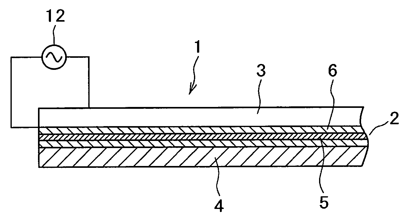
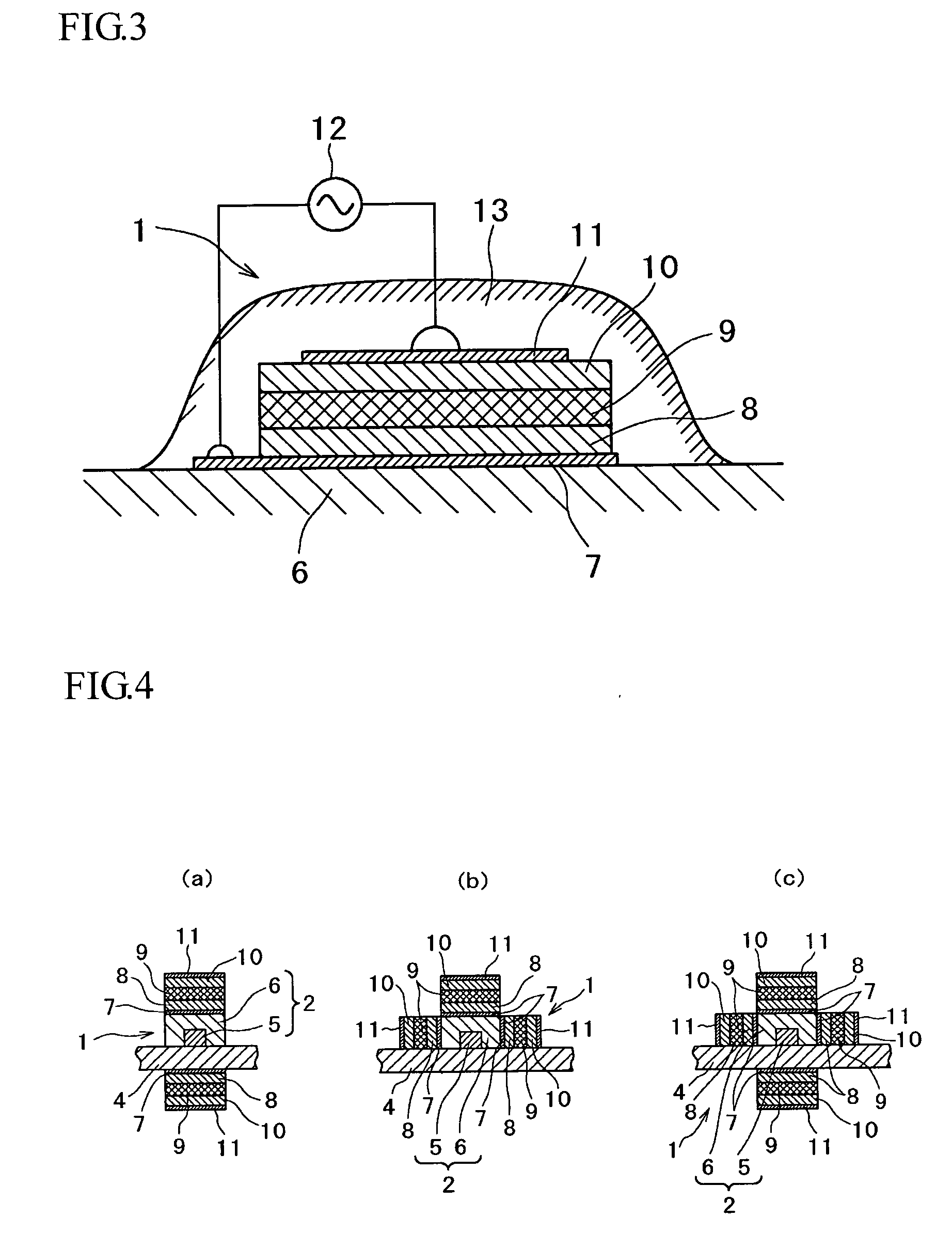
[0052] FIGS. 1 to 3 are typical views showing conceptually the waveguide optical amplifier of this invention. FIG. 1 is a longitudinal sectional view. FIG. 2 is a perspective sectional view. FIG. 3 is a cross sectional view of an important portion.

[0053] As shown in these drawings, in the waveguide optical amplifier 1 of this invention, a surface light emission source 3 for pumping driven electrically is provided adjacently to and integrally with an optical waveguide 2 doped with a rare earth element such as erbium as a light-emitting species, in the longitudinal direction of the optical waveguide.

[0054] Symbol 4 denotes a substrate, and the optical waveguide 2 and the surface light emission source for pumping 3 are arrayed on the substrate 4, to constitute the waveguide optical amplifier 1.

[0055] The substrate 4 is made of, for example, silica-based glass.

[0056] On the other hand, the optical waveguide 2 consists of a core 5 and a clad 6, and can be produced using the conventio...


PUM


Abstract

The conventional EDFA has such problems that it is very costly since it requires an external high-energy laser diode and an optical coupling means for optically coupling the pumping light given from the laser diode, and that it must have a long length for obtaining a desired amplification degree. A constitution having an optical waveguide and an pumping light source integrated for solving the problems is also proposed, but it also has a problem in view of downsizing.
This invention proposes a waveguide optical amplifier 1, in which a surface light emission source 3 for pumping driven electrically is provided adjacently to and integrally with an optical waveguide 2 doped with a light-emitting species, in the longitudinal direction of the optical waveguide.

Description

FIELD OF THE INVENTION [0001] The present invention relates to a waveguide optical amplifier applicable, for example, to an optical fiber communication system. BACKGROUND OF THE INVENTION [0002] Recently high-speed broadband subscribers' networks such as ADSL, CATV and FTTH are widely used, and in this connection, it has become important to improve Metro Networks, for example, by enhancing their capacities. For the improvement of Metro Networks, it is urgently demanded that the optical amplifier used as a key device in the optical fiber communication system allows easier handling and is downsized. [0003] As a typical conventional optical amplifier for a long-distance transmission line of an optical fiber communication system, an erbium-doped fiber amplifier (EDFA) is known. [0004] Examples of known erbium-doped fiber amplifiers are disclosed in U.S. Pat. Nos. 5,271,024, No. 5,636,301 and No. 5,768,012 etc. [0005] For example as shown in the conceptual view of FIG. 10, the EDFA is ba...

Claims


Application Information

Patent Timeline
Patent Type & Authority Applications(United States)
IPC IPC(8): H01S3/00H01S3/063H01S3/0915
CPCH01S3/0915H01S3/063
Inventor KAWAZOE, HIROSHIMUTA, KENICHI
Owner KAWAZOE HIROSHI
Why Eureka
Try Eureka