Stent delivery system having delivery catheter member with a clear transition zone

a technology of transition zone and stent, which is applied in the field of expandable intraluminal medical devices, can solve the problems of inability to use stents in some vessels, inability to meet the needs of patients,

Inactive Publication Date: 2005-09-13
CARDINAL HEALTH SWITZERLAND 515 GMBH
View PDF22 Cites 54 Cited by
  • Summary
  • Abstract
  • Description
  • Claims
  • Application Information

AI Technical Summary

Benefits of technology

[0019]In accordance with one aspect of the present invention, there is provided a medical device delivery system for using an expandable medical device within the body which includes an outer sheath comprising an elongated tubular body member and a distal section having a proximal end bonded to the distal end of the tubular body member. In addition, the distal section formed from a clear polymeric material, such as a clear nylon material, so as to make possible the visual inspection of an implantable medical device positioned beneath or within the distal section of the outer sheath. In addition, the delivery system includes an inner shaft located coaxially within the outer sheath and an implantable medical device located within the relatively clear distal section of the outer sheath. The inner shaft serves the purpose of providing for the delivery of the medical device.

Problems solved by technology

However, such stents are often impractical for use in some vessels such as the carotid artery.
A patient having a balloon expandable stent made from stainless steel or the like, placed in their carotid artery might be susceptible to severe injury through day to day activity.
A sufficient force placed on the patient's neck, such as by falling, could cause the stent to collapse, resulting in injury to the patient.
Designing delivery systems for delivering self-expanding stents has proven difficult.
However, delivering the stent through the entire length of the catheter can cause many problems, including possible damage to a vessel or the stent during its travel.
In addition, it is often difficult to design a pusher having enough flexibility to navigate through the catheter, but also enough stiffness to push the stent out of the catheter.
Except this in itself has posed some problems.
When this happens, the catheter has difficulty sliding over the stent during delivery.
This situation can result in the stent becoming stuck inside the catheter, or could damage the stent during delivery.
However, withdrawing the flexible hose over the stent during expansion could also cause damage to the stent.
As explained below, large sized outer sheaths can pose obstacles to the physician.
Another problem associated with prior stent delivery systems is caused by the fact that prior to being inserted into the body the stent is entirely covered by an opaque delivery catheter and it is not possible for the physician to visually observe the stent prior to insertion into the body.
For example, the physician is unable to visually observe the length of the stent.
In addition, the physician is unable to visually observe the location or position of the stent with the catheter, and for that matter, the physician is unable to even visually confirm that a stent is present within the delivery catheter.

Method used


Image

  • Stent delivery system having delivery catheter member with a clear transition zone
  • Stent delivery system having delivery catheter member with a clear transition zone
  • Stent delivery system having delivery catheter member with a clear transition zone

Examples


Embodiment Construction

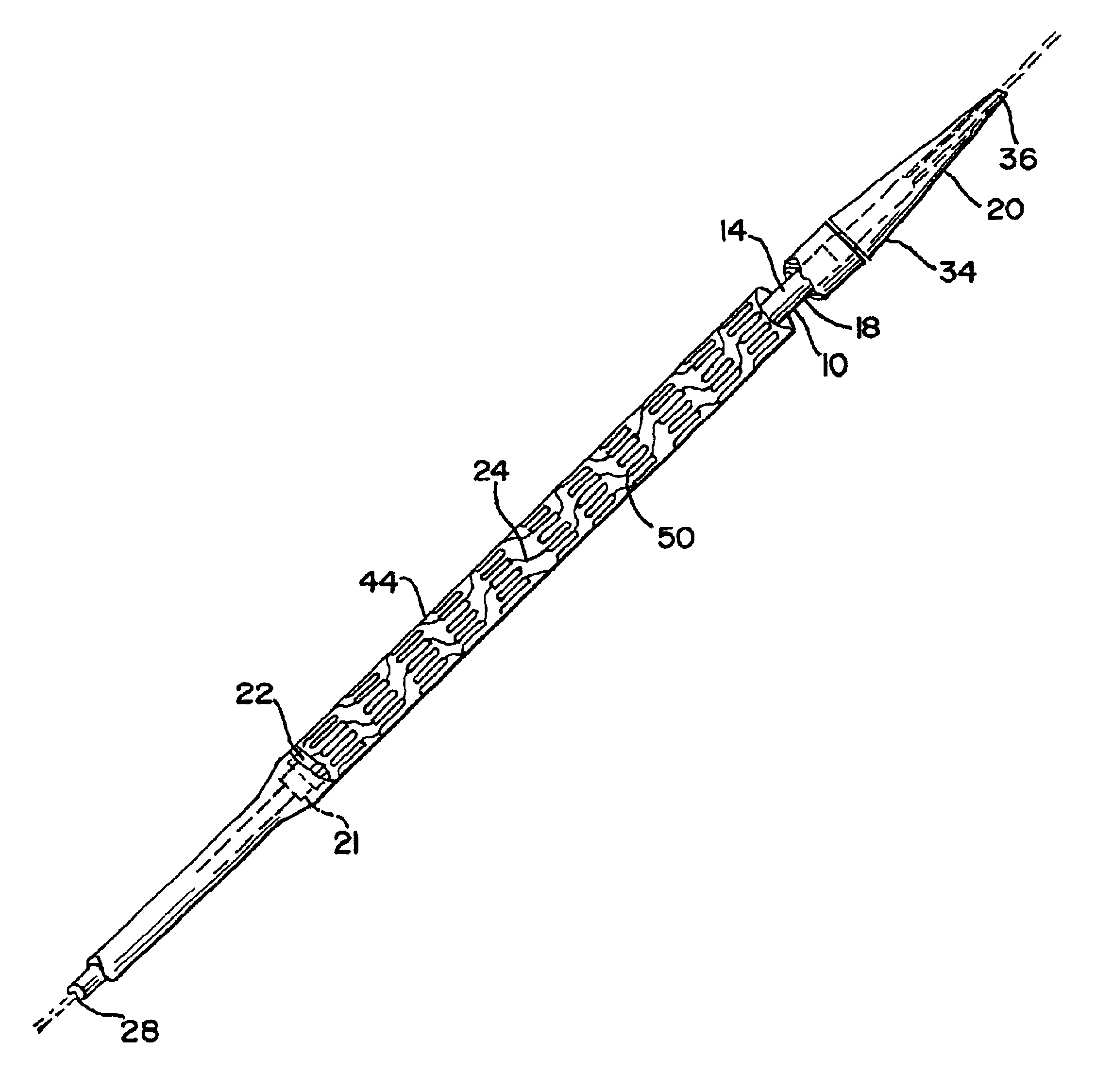
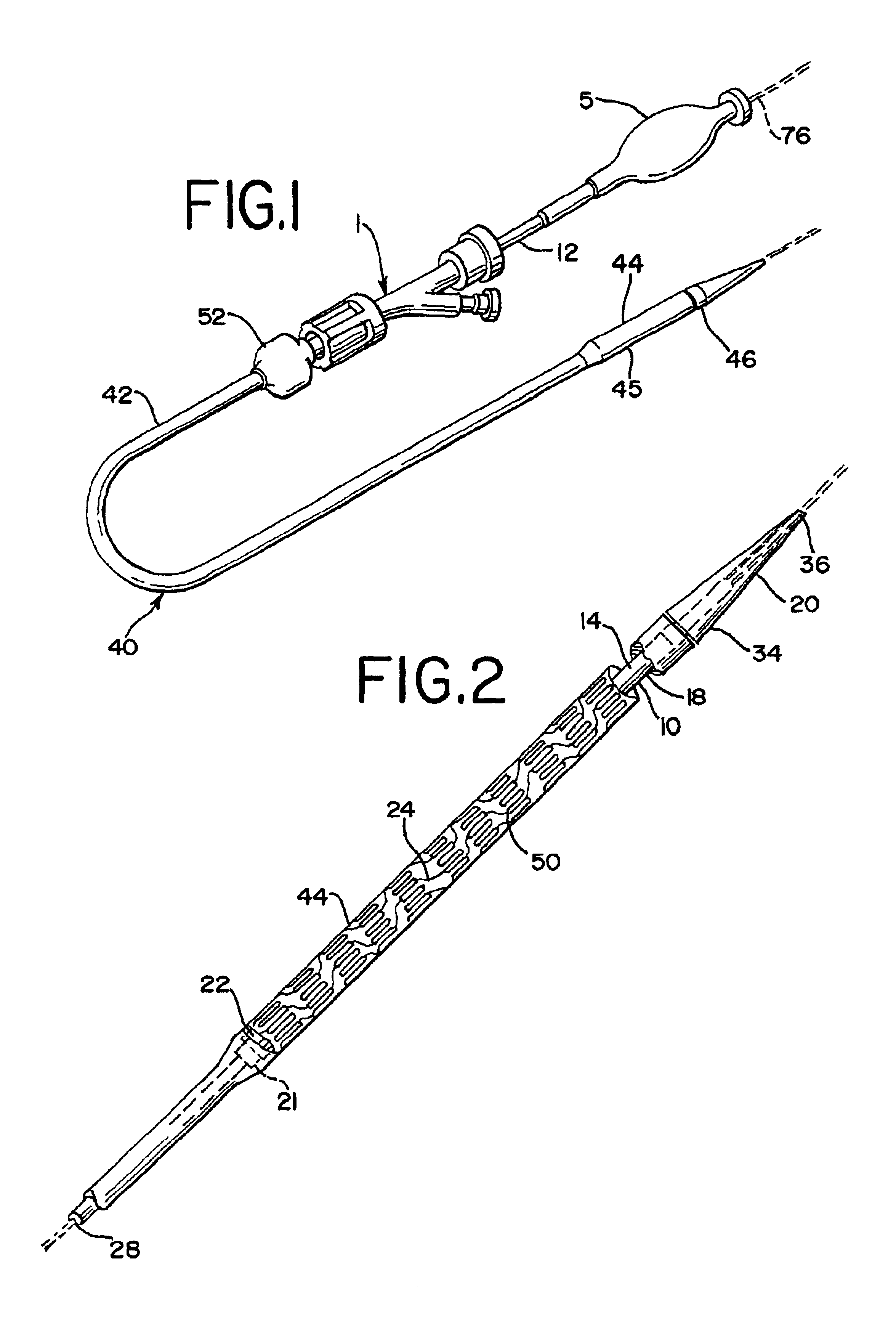
[0028]Referring now to the Figures wherein like numerals indicate the same element throughout the views, there is shown in FIGS. 1 and 2 a self-expanding stent delivery system 1 made in accordance with the present invention. System 1 comprises inner and outer coaxial tubes. The inner tube will be referred to as the shaft 10 and the outer tube will be referred to as the sheath 40. Shaft 10 has proximal and distal ends 12 and 14 respectively. The proximal end 12 of the shaft has a Luer guidewire hub 5 attached thereto. The shaft 10 has a proximal portion which is preferably made from a relatively stiff material such as stainless steel, Nitinol, or any other suitable material known to those of ordinary skill in the art. The shaft 10 also includes a distal portion 18 which is preferably made from a co-extrusion high density polyethylene for the inner portion and polyamide for the outer portion. Other suitable materials for distal portion 18 known to those of ordinary skill in the art in...


PUM


Abstract

A catheter based stent placement system in which the catheter has a clear or translucent transition zone for visual inspection of the stent when placed in the catheter.

Description

[0001]This application claims benefit to provisional application 60 / 185,798 filed Feb. 29, 2000.FIELD OF THE INVENTION[0002]The present invention relates to an expandable intraluminal medical device, for example a stent, for use within a body passageway for repairing blood vessels narrowed or occluded by disease. More particularly, the present invention relates to a system for delivering such stents.RELATED PATENT APPLICATION[0003]The present invention is an improvement of the stent delivery system disclosed in co-pending U.S. patent application Ser. No. 09 / 243,750, entitled, “A Delivery Apparatus For A Self Expanding Stent,” filed Feb. 3, 1999, assigned to the same assignee as the subject patent application, and hereby incorporates by reference.BACKGROUND OF THE INVENTION[0004]Percutaneous transluminal coronary angioplasty (PTCA) is a therapeutic medical procedure used to increase blood flow through the coronary artery and can often be used as an alternative to coronary by-pass sur...

Claims


Application Information

Patent Timeline
Patent Type & Authority Patents(United States)
IPC IPC(8): A61F2/06A61F2/84
CPCA61F2/95A61F2/966
Inventor BARTHOLF, HEATHER A.GRAHAM, ROBERT F.
Owner CARDINAL HEALTH SWITZERLAND 515 GMBH
Why Eureka
Try Eureka