
CMOS/MEMS integrated ink jet print head and method of forming same

a liquid ink jet and print head technology, applied in the field of digital control printing devices, can solve the problems of high-voltage drive circuitry, large piezoelectric crystal arrays, and large number of nozzles per print head unit length, and achieve the effect of improving manufacturability and reducing cos

Inactive Publication Date: 2005-09-13
EASTMAN KODAK CO
View PDF3 Cites 79 Cited by
  • Summary
  • Abstract
  • Description
  • Claims
  • Application Information

AI Technical Summary

Benefits of technology

[0021]It is therefore an object of the invention to provide a CIJ printhead that may be fabricated at lower cost and improved manufacturability as compared to those ink jet printheads known in the prior art that require more custom processing.
[0024]In accordance with a second aspect of the invention, there is provided a method of operating a continuous ink jet printhead comprising providing a silicon substrate having an integrated circuit formed therein for controlling operation of the print head, the silicon substrate having one or more ink channels formed therein, the silicon substrate being covered by one or more insulating layers having a channel formed therein and terminating at a nozzle opening, the surface of the printhead being relatively planar for facilitating maintenance of the printhead around the nozzle openings; moving ink under pressure from the one or more channels formed in the silicon substrate to a respective ink channel formed in the insulating layer or layers; and asymmetrically heating the ink at the nozzle opening formed in a relatively thin membrane formed covering the insulating layer or layers to affect deflection of ink droplet(s), each nozzle communicating with an ink channel formed in the insulating layer or layers.
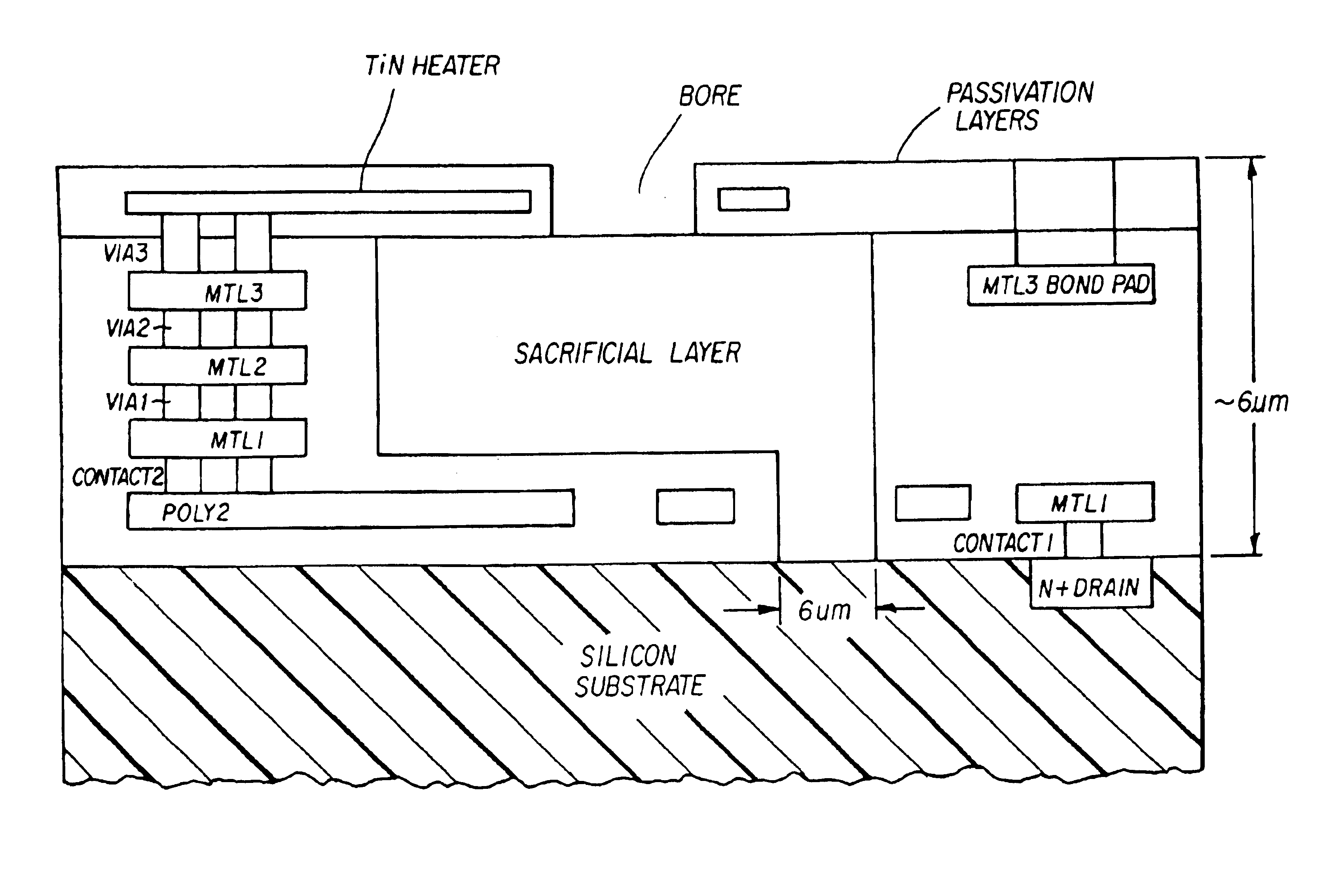
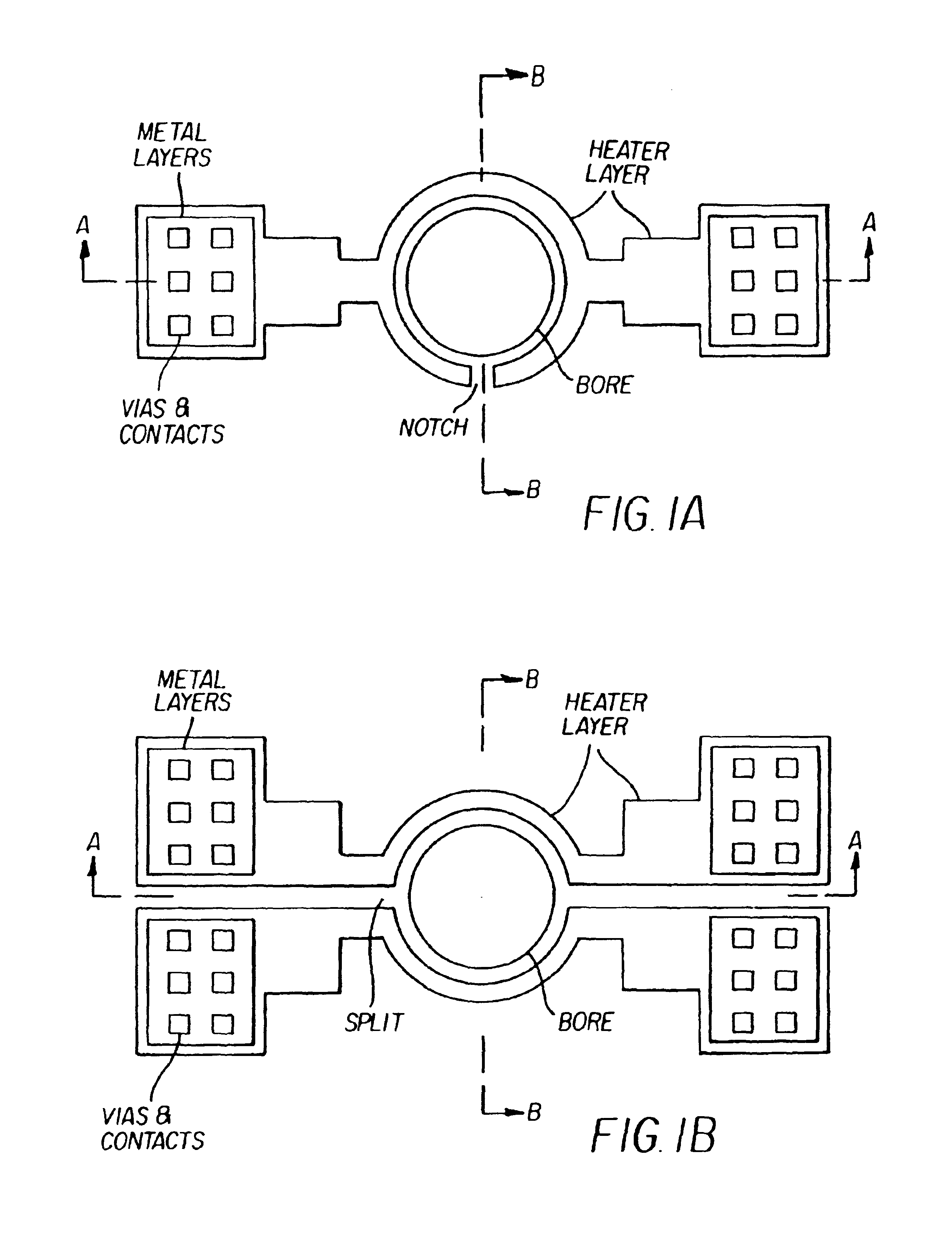
[0025]In accordance with a third aspect of the invention, there is provided a method of forming a continuous ink jet print head comprising providing a silicon substrate having an integrated circuit for controlling operation of the print head, the silicon substrate having an insulating layer or layers formed thereon, the insulating layer or layers having electrical conductors formed therein that are electrically connected to circuits formed in the silicon substrate, forming in the insulating layer or layers a series of relatively large bores each of which extends from the surface of the insulating layer or layers to the silicon substrate, depositing a sacrificial layer in each of the series of bores; forming over the sacrificial layer in each bore an insulating layer or layers that include a heater element; forming a nozzle opening in the insulating layer or layers that include a heater element; and removing the sacrificial layer from each of the bores to form a print head having a relatively planar surface around the area of the nozzle bores to facilitate maintenance of the printhead.

Problems solved by technology

However, piezoelectric printing mechanisms usually require complex high voltage drive circuitry and bulky piezoelectric crystal arrays, which are disadvantageous in regard to number of nozzles per unit length of print head, as well as the length of the print head.
Thermal ink jet printing typically requires that the heater generates an energy impulse enough to heat the ink to a temperature near 400° C. which causes a rapid formation of a bubble.
The high temperatures needed with this device necessitate the use of special inks, complicates driver electronics, and precipitates deterioration of heater elements through cavitation and kogation.
Such encrusted debris interferes with the thermal efficiency of the heater and thus shorten the operational life of the print head.
The charging and deflection mechanisms are bulky and severely limit the number of nozzles per print head.
As is well-known in the art of semiconductor manufacture, it is undesirable from the point of view of reliability to pass current bearing liquids in contact with semiconductor surfaces.
Thus the manufacture of continuous ink jet print heads has not been generally integrated with the manufacture of CMOS circuitry.
Although solvent-based (particularly alcohol-based) inks have quite good deflection patterns (see in this regard U.S. application Ser. No. 09 / 451,790 filed in the names of Trauernicht et al), and achieve high image quality in asymmetrically heated continuous ink jet printers, water-based inks are more problematic.
The water-based inks do not deflect as much, thus their operation is not robust.
There are two major difficulties in realizing page wide and high productivity ink jet print heads.
The second is that the drivers providing the power to the heaters and the electronics controlling each nozzle must be integrated with each nozzle, since attempting to make thousands of bonds or other types of connections to external circuits is presently impractical.

Method used


Image

  • CMOS/MEMS integrated ink jet print head and method of forming same
  • CMOS/MEMS integrated ink jet print head and method of forming same
  • CMOS/MEMS integrated ink jet print head and method of forming same

Examples


Embodiment Construction

[0055]This description will be directed in particular to elements forming part of, or cooperating more directly with, apparatus in accordance with the present invention. It is to be understood that elements not specifically shown or described may take various forms well known to those skilled in the art.

[0056]Referring to FIG. 20, a continuous ink jet printer system is generally shown at 10. The printhead 10a, from which extends an array of nozzles 20, incorporating heater control circuits (not shown).

[0057]Heater control circuits read data from an image memory, and send time-sequenced electrical pulses to the heaters of the nozzles of nozzle array 20. These pulses are applied an appropriate length of time, and to the appropriate nozzle, so that drops formed from a continuous ink jet stream will form spots on a recording medium 13, in the appropriate position designated by the data sent from the image memory. Pressurized ink travels from an ink reservoir (not shown) to an ink delive...


PUM

PropertyMeasurementUnit
thicknessaaaaaaaaaa
temperatureaaaaaaaaaa
voltagesaaaaaaaaaa

Abstract

An ink jet print head is formed of a silicon substrate that includes an integrated circuit formed therein for controlling operation of the print head. The silicon substrate has one or more ink channels formed therein along the longitudinal direction of the noble array. An insulating layer or layers overlie the silicon substrate and has a series or an array of nozzle openings or bores formed therein along the length of the substrate and each nozzle opening communicates with an ink channel. The area comprising the nozzle openings forms a generally planar surface to facilitate maintenance of the printhead. A heater element is associated with each nozzle opening or bore for asymmetrically heating ink as ink passes through the nozzle opening or bore.

Description

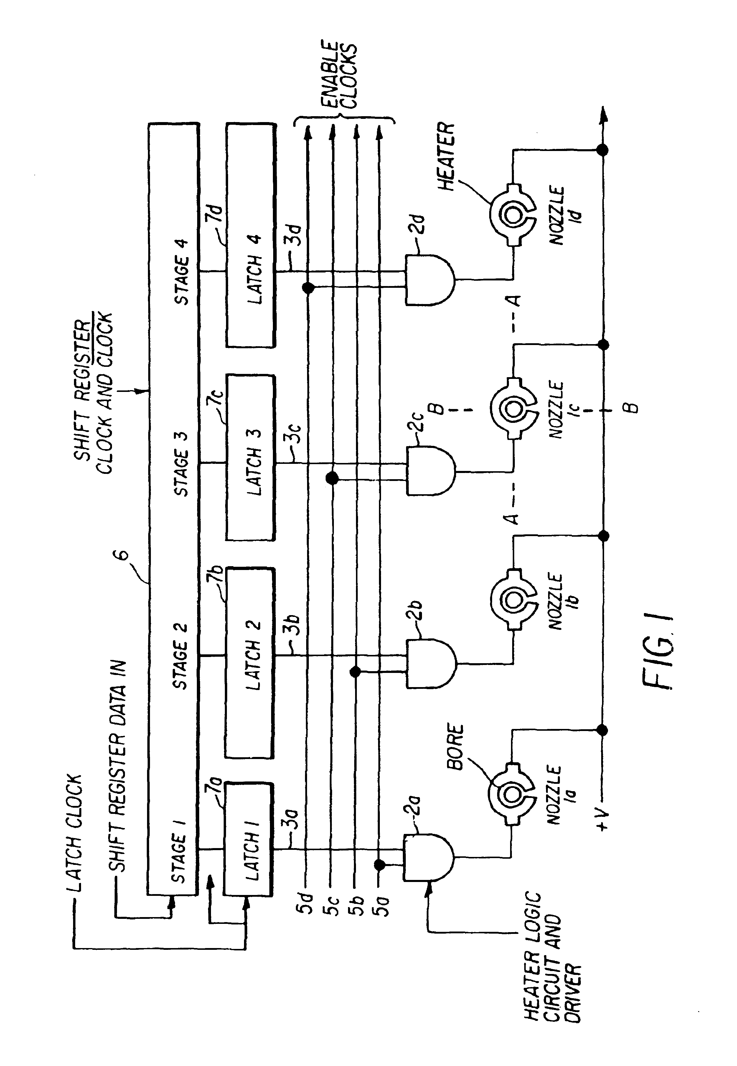
CROSS REFERENCE TO RELATED APPLICATION[0001]This is a Divisional application of U.S. application Ser. No. 09 / 792,114, filed Feb. 22, 2001 now U.S. Pat. No. 6,502,925, entitled; CMOS / MEMS INTEGRATED INK JET PRINT HEAD AND METHOD OF FORMING SAME.FIELD OF THE INVENTION[0002]This invention generally relates to the field of digitally controlled printing devices, and in particular to liquid ink print heads which integrate multiple nozzles on a single substrate and in which a liquid drop is selected for printing by thermo-mechanical means.BACKGROUND OF THE INVENTION[0003]Ink jet printing has become recognized as a prominent contender in the digitally controlled, electronic printing arena because, e.g., of its non-impact, low noise characteristics and system simplicity. For these reasons, ink jet printers have achieved commercial success for home and office use and other areas.[0004]Ink jet printing mechanisms can be categorized as either continuous (CIJ) or Drop-on-Demand (DOD). U.S. Pat. ...

Claims


Application Information

Patent Timeline
Patent Type & Authority Patents(United States)
IPC IPC(8): B41J2/07B41J2/03B41J2/015B41J2/105
CPCB41J2/03B41J2/105B41J2002/032B41J2202/13B41J2202/16B41J2202/22
Inventor ANAGNOSTOPOULOS, CONSTANTINE N.LEBENS, JOHN A.TRAUERNICHT, DAVID P.CHWALEK, JAMES M.DELAMETTER, CHRISTOPHER N.
Owner EASTMAN KODAK CO
Learn More