Magnetic random access memory designs with controlled magnetic switching mechanism by magnetostatic coupling

a random access memory and magnetic switching technology, applied in the field of magnetic random access memory, can solve the problems of adverse effect on the storage and reading of data, uncontrollable edge-fields, and large size associations, and achieve the effects of reducing edge effects, small, but non-zero, magnetic moment, and reducing probability

Inactive Publication Date: 2005-09-13
HEADWAY TECH INC
View PDF6 Cites 42 Cited by
  • Summary
  • Abstract
  • Description
  • Claims
  • Application Information

AI Technical Summary

Benefits of technology

[0007]In order for the MTJ MRAM device to be competitive with other forms of DRAM, it is necessary that the MTJ be made very small, typically of sub-micron dimension. Parkin et al. (U.S. Pat. No. 6,166,948) notes that sub-micron dimensions are needed to be competitive with DRAM memories in the range of 10-100 Mbit capacities. Parkin also notes that such small sizes are associated with significant problems, particularly super-paramagnetism, which is the spontaneous thermal fluctuation of magnetization produced by in samples of ferromagnetic material too small to have sufficient magnetic anisotropy (a measure of the ability of a sample to maintain a given magnetization direction). Another size-related problem results from non-uniform and uncontrollable edge-fields produced by shape-anisotropy (a property of non-circular samples). As the cell size decreases, these edge fields become relatively more important than the magnetization of the body of the cell and have an adverse effect on the storage and reading of data. Although such shape-anisotropies, when of sufficient magnitude, reduce the disadvantageous effects of super-paramagnetism, they have the negative effect of requiring high currents to change the magnetization direction of the MTJ for the purpose of storing data. To counteract these edge effects, Shi et al. (U.S. Pat. No. 5,757,695) teaches the formation of an ellipsoidal MTJ cell wherein the magnetization vectors are aligned along the length (major axis) of the cell and which do not present variously oriented edge domains, high fields and poles at the ends of the element.
[0008]MTJ devices have been fabricated in several configurations, one type comprising a free ferromagnetic layer separated from a fixed (or pinned) layer. In such a configuration, the MTJ has data stored in it by causing the magnetization of its free layer to be either parallel or antiparallel to that of the pinned layer. The pinned layer may itself be a composite layer formed of two ferromagnetic layers held in an antiparallel magnetization configuration by some form of magnetic coupling so that it presents a zero or negligible net magnetic moment to the MTJ. Such an arrangement is advantageous in reducing edge effects due to anisotropies. Parkin, cited above, teaches an improved MTJ cell utilizing a free layer that comprises two ferromagnetic layers that are coupled by their dipolar fields in an antiparallel magnetization configuration to produce a small, but non-zero, magnetic moment. When written on by an external applied magnetic field, the two magnetic moments switch directions simultaneously so that the net magnetic moment of the free layer switches direction relative to the pinned layer.
[0009]It is undesirable for MTJ devices to have excessive magnetic coupling between adjacent magnetic layers of neighboring devices or even within the same device as this coupling must be overcome when writing on the device. As noted above, edge anisotropies are one source of undesirable coupling. Another source results from non-planar surfaces at the interfaces of ferromagnetic layers, such as might occur between the fixed and free layer of an MTJ. This is known as topological coupling. Chen et al. (U.S. Pat. No. 6,376,260 B1) teach an improved fabrication method in which the magnetic element includes a first electrode (a fixed layer), a second electrode (a free layer) and a spacer layer between them. The thicknesses of the first and second electrodes are in a special relationship to each other such that the net magnetic field at the interface between the free and spacer layers is zero.
[0010]Koch et al. (U.S. Pat. No. 6,005,800) deal with the problem that results when writing to one specific cell also affects the magnetization directions of adjacent cells that are not being addressed. Koch teaches the formation of cells with two shapes, which are mirror images of each other. The cells are arranged in a checkerboard pattern, so that a cell of one shape is surrounded by cells of the other shape. Since neighboring cells thereby have their preferred magnetization vectors oriented differently, there is a reduced probability that writing to one cell type will affect the magnetization of the other type.
[0011]As has been discussed, many of the problems associated with the construction of MRAM arrays are related to the shapes of the cells. Cell shapes of present designs are typically single element rectangle, elliptical or lozenge. Any irregularities of these shapes, or defects at their edges produced during their formation, will result in coercivity fluctuations distributed throughout the array. It is the object of the present invention to control the problem of undesirable edge effects more effectively than in the prior art by dividing single elements into multi-sections, thus providing nucleation sites at which switching can occur and whose presence will dominate the adverse affects of unintentionally generated shape irregularities or edge defects.SUMMARY OF THE INVENTION
[0012]A first object of this invention is to provide a novel MTJ device whose magnetization switching properties are insensitive to shape irregularities and edge defects and which can be used to form an MRAM array.

Problems solved by technology

Parkin also notes that such small sizes are associated with significant problems, particularly super-paramagnetism, which is the spontaneous thermal fluctuation of magnetization produced by in samples of ferromagnetic material too small to have sufficient magnetic anisotropy (a measure of the ability of a sample to maintain a given magnetization direction).
Another size-related problem results from non-uniform and uncontrollable edge-fields produced by shape-anisotropy (a property of non-circular samples).
As the cell size decreases, these edge fields become relatively more important than the magnetization of the body of the cell and have an adverse effect on the storage and reading of data.
Although such shape-anisotropies, when of sufficient magnitude, reduce the disadvantageous effects of super-paramagnetism, they have the negative effect of requiring high currents to change the magnetization direction of the MTJ for the purpose of storing data.
It is undesirable for MTJ devices to have excessive magnetic coupling between adjacent magnetic layers of neighboring devices or even within the same device as this coupling must be overcome when writing on the device.
As noted above, edge anisotropies are one source of undesirable coupling.
As has been discussed, many of the problems associated with the construction of MRAM arrays are related to the shapes of the cells.
Any irregularities of these shapes, or defects at their edges produced during their formation, will result in coercivity fluctuations distributed throughout the array.

Method used


Image

  • Magnetic random access memory designs with controlled magnetic switching mechanism by magnetostatic coupling
  • Magnetic random access memory designs with controlled magnetic switching mechanism by magnetostatic coupling
  • Magnetic random access memory designs with controlled magnetic switching mechanism by magnetostatic coupling

Examples


Embodiment Construction

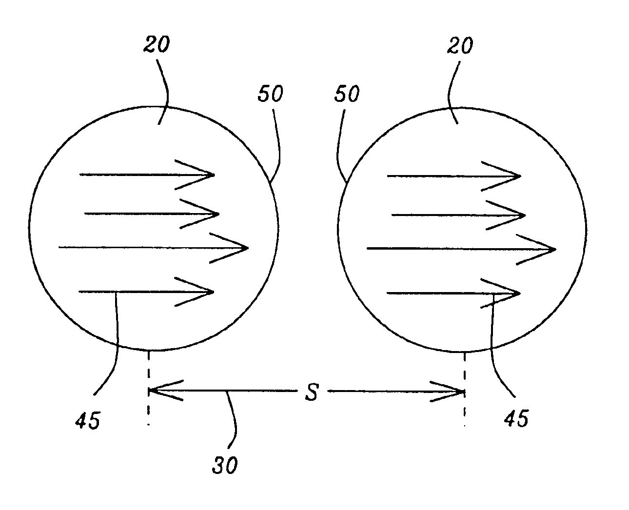
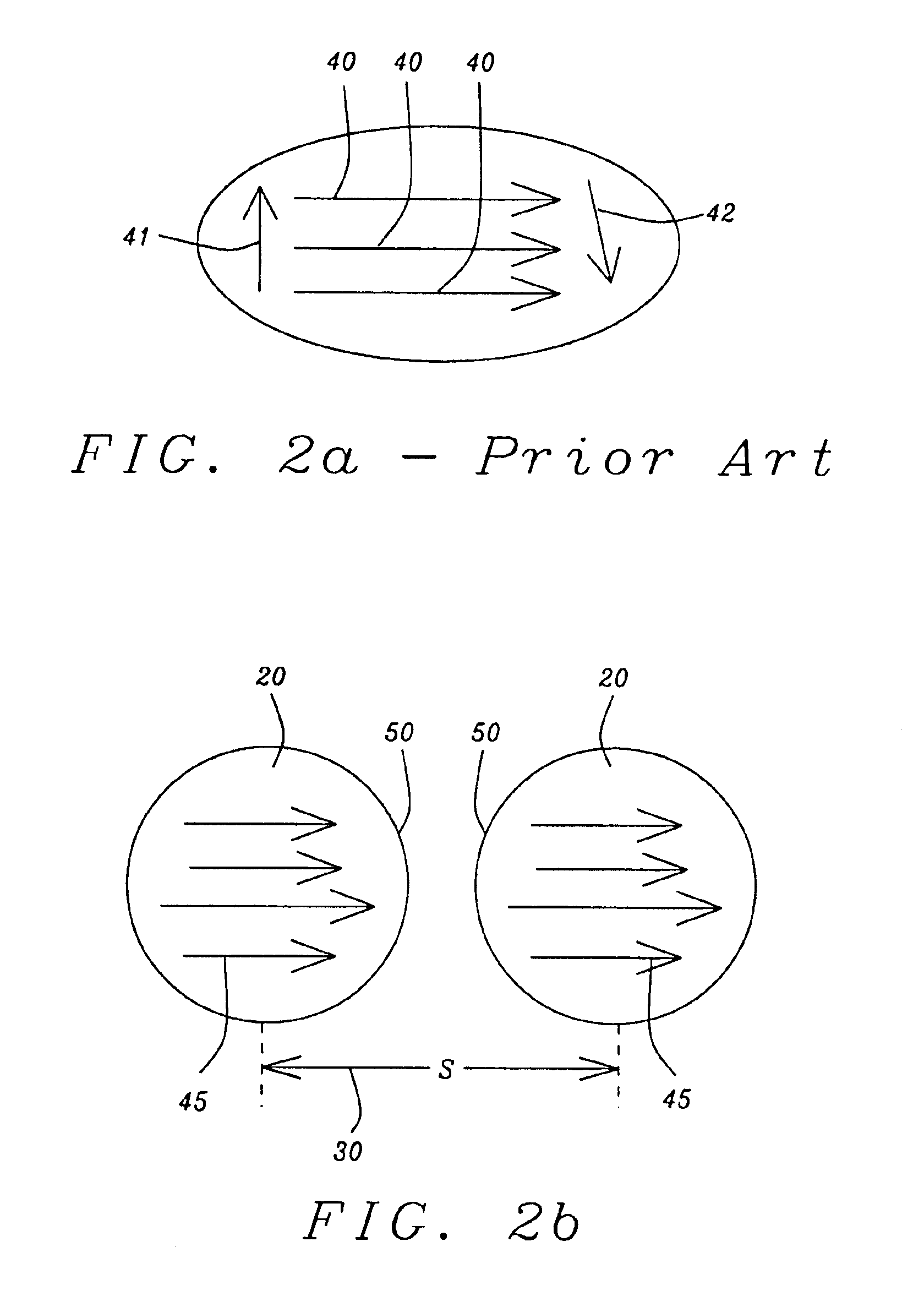
[0027]The preferred embodiment of the present invention teaches a method of forming an MRAM cell array of novel segmented MTJ devices of approximately sub-micron dimensions, said array thereby having a structure and design that provides a lowered threshold for state switching and a uniformity of coercivity across the array. The design of the array replaces a single MTJ cell element, such as is found with various shapes in the prior art, with elements which are formed of magnetostatically coupled discrete segments. These discrete elements are linked in chainlike configurations such as those shown in FIGS. 1a-d. The segmentation offers at least the following three advantages: 1) a reduction of the switching field threshold dependence on individual cell geometry and a corresponding ability to control write power consumption by varying the direction of crystalline anisotropy; 2) a preferred path of switching which is a fanning mode, wherein the ends of the magnetization vectors of indiv...


PUM

PropertyMeasurementUnit
aspect ratioaaaaaaaaaa
sizeaaaaaaaaaa
sizeaaaaaaaaaa

Abstract

A magnetic tunneling junction (MTJ) memory cell for a magnetic random access memory (MRAM) array is formed as a chain of magnetostatically coupled segments. The segments can be circular, elliptical, lozenge shaped or shaped in other geometrical forms. Unlike the isolated cells of typical MTJ designs which exhibit curling of the magnetization at the cell ends and uncompensated pole structures, the present multi-segmented design, with the segments being magnetostatically coupled, undergoes magnetization switching at controlled nucleation sites by the fanning mode. As a result, the multi-segmented cells of the present invention are not subject to variations in switching fields due to shape irregularities and structural defects.

Description

RELATED PATENT APPLICATION[0001]This application is related to Ser. No. 10 / 647,716, filing date (Aug. 25, 2003), assigned to the same assignee as the current invention.BACKGROUND OF THE INVENTION[0002]1. Field of the Invention[0003]This invention relates to the use of magnetic tunnel junctions (MTJ) as storage elements (cells) in non-volatile memory cell arrays, called magnetic random access memories (MRAM). In particular it relates to MRAM arrays whose cells consist of chains of magnetostatically coupled segments, the design providing artificial nucleation sites for uniform magnetic switching between multi-stable states.[0004]2. Description of the Related Art[0005]The magnetic tunnel junction (MTJ) basically comprises two electrodes, which are layers of ferromagnetic material, separated by a tunnel barrier layer, which is a thin layer of insulating material. The tunnel barrier layer must be sufficiently thin so that there is a probability for charge carriers (typically electrons) t...

Claims


Application Information

Patent Timeline
Patent Type & Authority Patents(United States)
IPC IPC(8): H01F41/30H01F10/00H01F10/32H01F41/14H01L43/08G11C11/16
CPCB82Y25/00B82Y40/00G11C11/16H01F10/3254H01F41/308H01L43/08H01F10/3272H10N50/10
Inventor MIN, TAIWANG, PO KANG
Owner HEADWAY TECH INC
Why Eureka
Try Eureka