High temperature superconductor tape RF coil for magnetic resonance imaging

a superconductor tape and magnetic resonance imaging technology, applied in the direction of superconductor devices, instruments, using reradiation, etc., can solve the problems of increasing the cost of the coil, limiting the geometry of the receiving coil to a surface coil configuration, and limiting the ability to handle a variety of imaging situations

Active Publication Date: 2005-09-13
HONG KONG THE UNIV OF +1
View PDF7 Cites 33 Cited by
  • Summary
  • Abstract
  • Description
  • Claims
  • Application Information

AI Technical Summary

Benefits of technology

[0010]Another embodiment of the present invention is directed to an HTS RF coil for an MRI device having a sample chamber, the HTS RF coil comprising: a coil holder sized to fit around the sample chamber; an HTS tape having a first end and a second end and a surface comprised essentially of high temperature superconductor, the HTS tape supported by the coil holder and enclosing the sample chamber; and a high-Q capacitor having a first contact and a second contact, the first end of the HTS tape in electrical contact with the first contact and the seco...

Problems solved by technology

The rigid substrate of the wafer supporting the HTS thin film, however, limits the geometry of the receiving coil to a surface coil configuration.
The restrictions caused by the rigid HTS film substrate further limits the ability to handle a variety o...

Method used


Image

  • High temperature superconductor tape RF coil for magnetic resonance imaging
  • High temperature superconductor tape RF coil for magnetic resonance imaging
  • High temperature superconductor tape RF coil for magnetic resonance imaging

Examples


Embodiment Construction

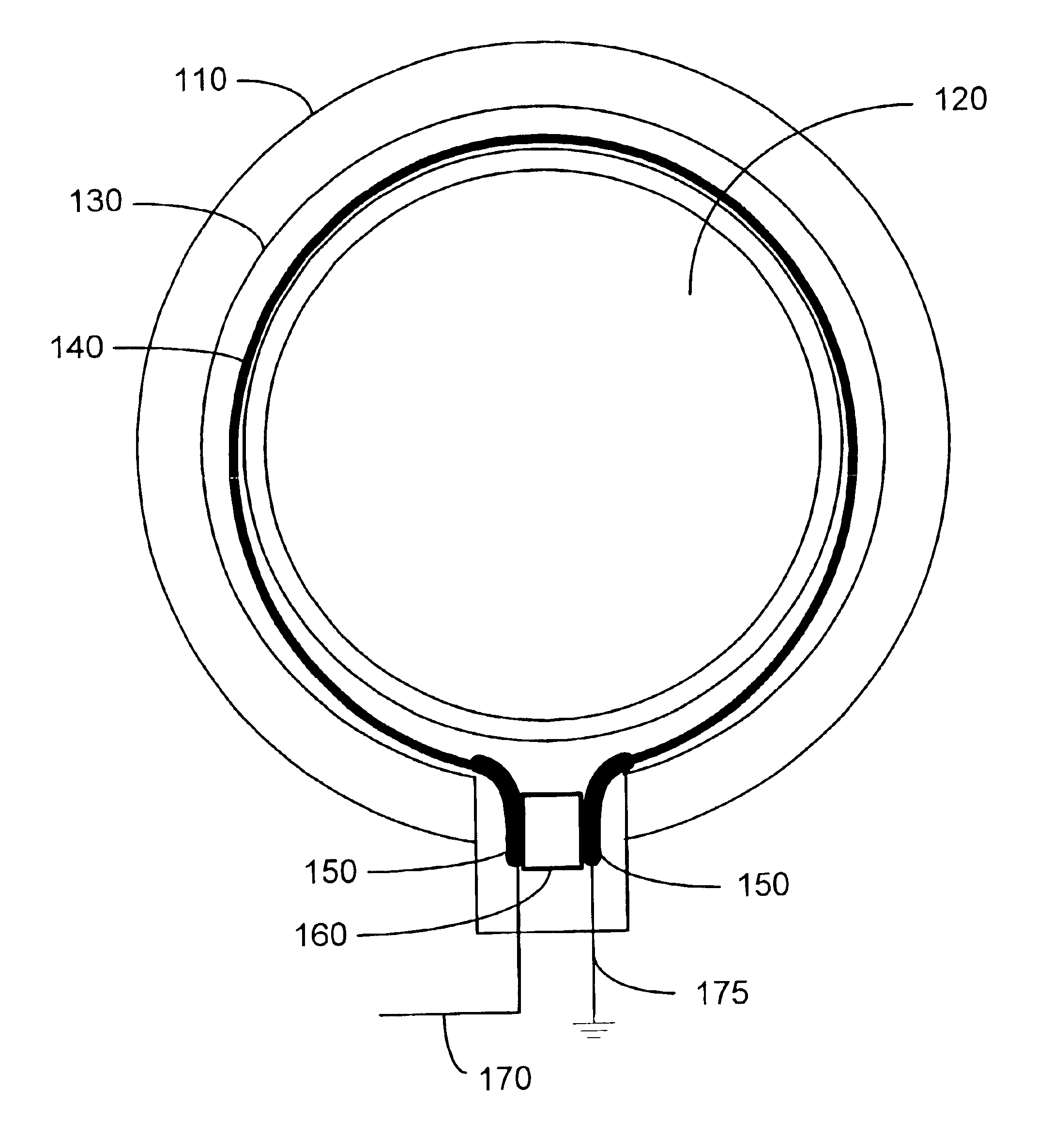
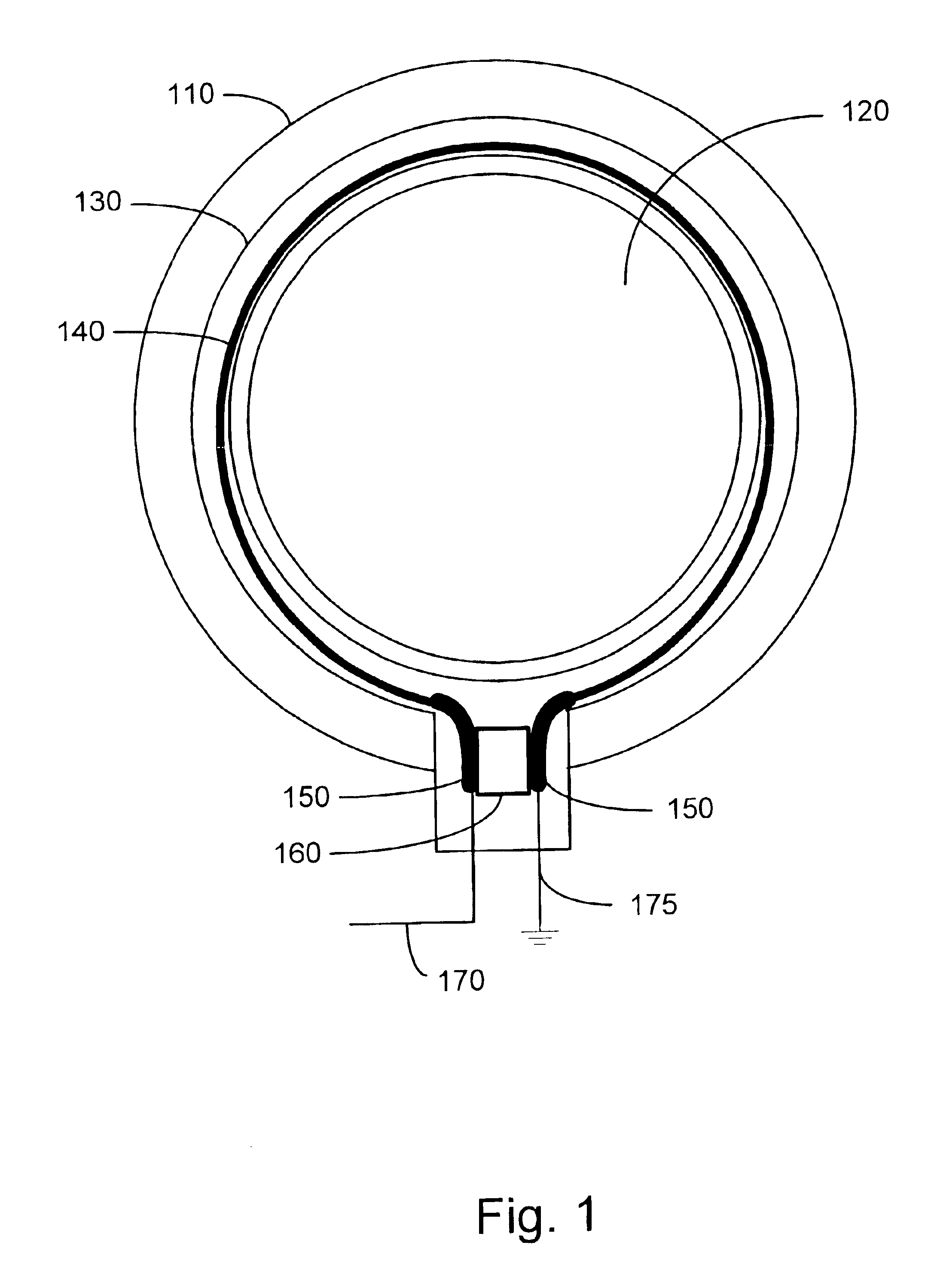
[0021]FIG. 1 is an illustration of one embodiment of the present invention. In the embodiment shown in FIG. 1, the coil holder 110 is an annular ring enclosing a test volume 120. The coil holder 110 has a circumferential groove 130 extending around the circumference of the coil holder 110. The superconducting coil 140 is disposed in the circumferential groove 130 and is supported by the coil holder. The superconducting coil 140 is formed as a loop having metal contacts 150 at each loop end. The metal contact 150 allows the ends of the loop to be soldered to a loop capacitor 160 and to a ground lead 175 and a signal processing lead 170.

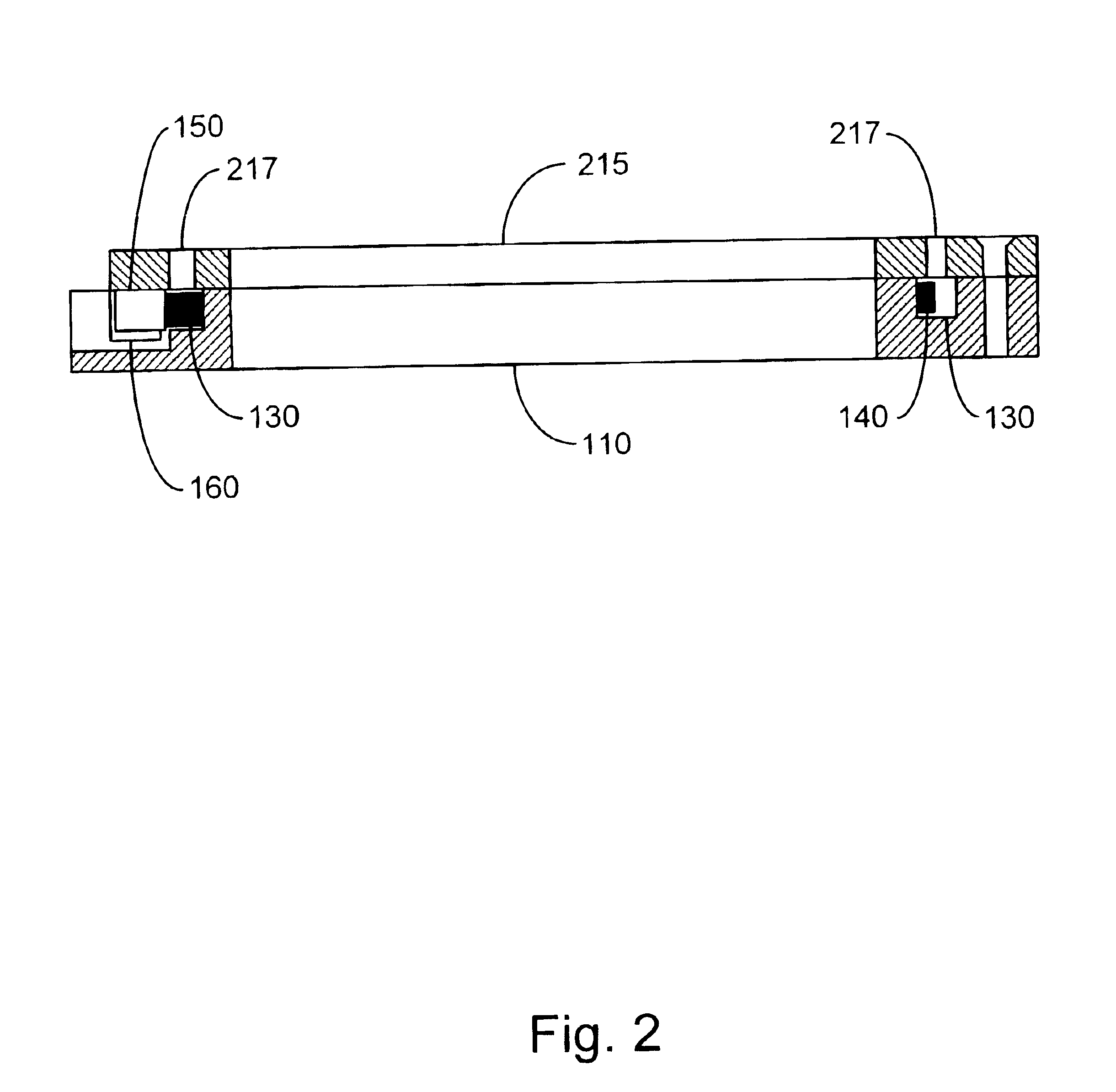
[0022]FIG. 2 is a side section view of the embodiment shown in FIG. 1. Superconducting coil 140 is disposed in the circumferential groove 130 of the coil holder 110. A holder cover 215 covers the circumferential groove 130 to retain the superconducting coil 140 within the groove 130. Through holes 217 in the cover 215 allow direct contact of the coolan...


PUM

PropertyMeasurementUnit
Fractionaaaaaaaaaa
Fractionaaaaaaaaaa
Temperatureaaaaaaaaaa

Abstract

A HTS RF coil is disclosed having at least a factor of three improvement in the SNR over a comparable copper coil and at least a factor of six improvement in Q over a comparable copper coil. A commercially available HTS tape is formed into a loop. High-Q capacitors are soldered across the loop ends. The silver sheath covering the tape is removed through chemical etching. The coil is placed in a holder for mechanical support and protection and covered with a cover having through holes enabling the coolant to directly contact the HTS coil.

Description

BACKGROUND OF THE INVENTION[0001]1. Field of the Invention[0002]The present invention relates to RF receiving coils for magnetic resonance imaging (MRI). More specifically, the invention relates to RF receiving coils incorporating high temperature superconductor (HTS) tapes.[0003]2. Description of the Related Art[0004]The receiver coil in an MRI device receives the signal emitted from the sample that is later converted into a 2-D image or 3-D model of the sample. The receiver coil usually sits inside the magnet and the gradient coils of the MRI device. Receiver coils are normally made of copper wire windings that exhibit a substantial resistance relative to the electrical resistance of the superconductor coils of the magnet or the gradient coils. It is believed that receiver coils employing superconductor materials would result in a higher Quality-factor and better MRI quality.[0005]Receiver coils made of HTS thin films have been fabricated and shown to exhibit a higher quality fact...

Claims


Application Information

Patent Timeline
IPC IPC(8): G01R33/34
CPCG01R33/341G01R33/34023
Inventor CHENG, FREDERICK M.C.LEE, FRANCIS K.H.YANG, EDWARD S.
Owner HONG KONG THE UNIV OF
Why Eureka
Try Eureka