Apparatus for and method of optical detection and analysis of an object

an object and optical detection technology, applied in the field of apparatus for optical detection and analysis, can solve the problems of interference pattern, inability to take into account the imperfection of the interface between, and the return combination of wavefronts is likely to be very complex, so as to achieve the effect of increasing the speed of detection

Inactive Publication Date: 2005-09-13
QINETIQ LTD
View PDF7 Cites 19 Cited by
  • Summary
  • Abstract
  • Description
  • Claims
  • Application Information

AI Technical Summary

Benefits of technology

[0041]Return pulses can conveniently be separated into very short time intervals of the order of femto- to nanoseconds by using a Time to Amplitude Converter (TAC) which will place return pulses received by the detector into time “bins” from which the target signature can be derived. The output from the TAC and signal processing electronics could be displayed graphically to allow identification to be performed by eye or more preferably the output can be analysed by a suitable computer program (similar to a sonar signature or drug spectrogram identification program) capable of identifying the signature with respect to a stored database of known target signatures.
[0042]Conveniently the speed of detection can be increased by making the apparatus cover a much wider field of view by either raster scanning or using an alternative detector such as a charge coupled detector array.

Problems solved by technology

However, this simple view of the interaction takes no account of the imperfection of the interface between the two materials.
This is because even in the simplest optical systems the returning combination of wavefronts is likely to be very complex due to multiple internal reflections.
If a highly coherent light source, such as a laser, is used then the reflected wavefronts will be able to vectorially add and subtract resulting in an interference pattern (this is due to the fact that spatial coherence means that the reflected wavefronts bear a fixed relationship to one another and are therefore able to optically interfere).
Attempting to use such an optical interference pattern as the “optical signature” will result in problems due to the short wavelength of light.
Secondly, the wavelength of light is much smaller than the path differences induced by the passage of a light beam through the atmosphere under normal meteorological conditions and any intereference pattern will therefore be swamped by fluctuations caused by the atmosphere.

Method used


Image

  • Apparatus for and method of optical detection and analysis of an object
  • Apparatus for and method of optical detection and analysis of an object
  • Apparatus for and method of optical detection and analysis of an object

Examples


Embodiment Construction

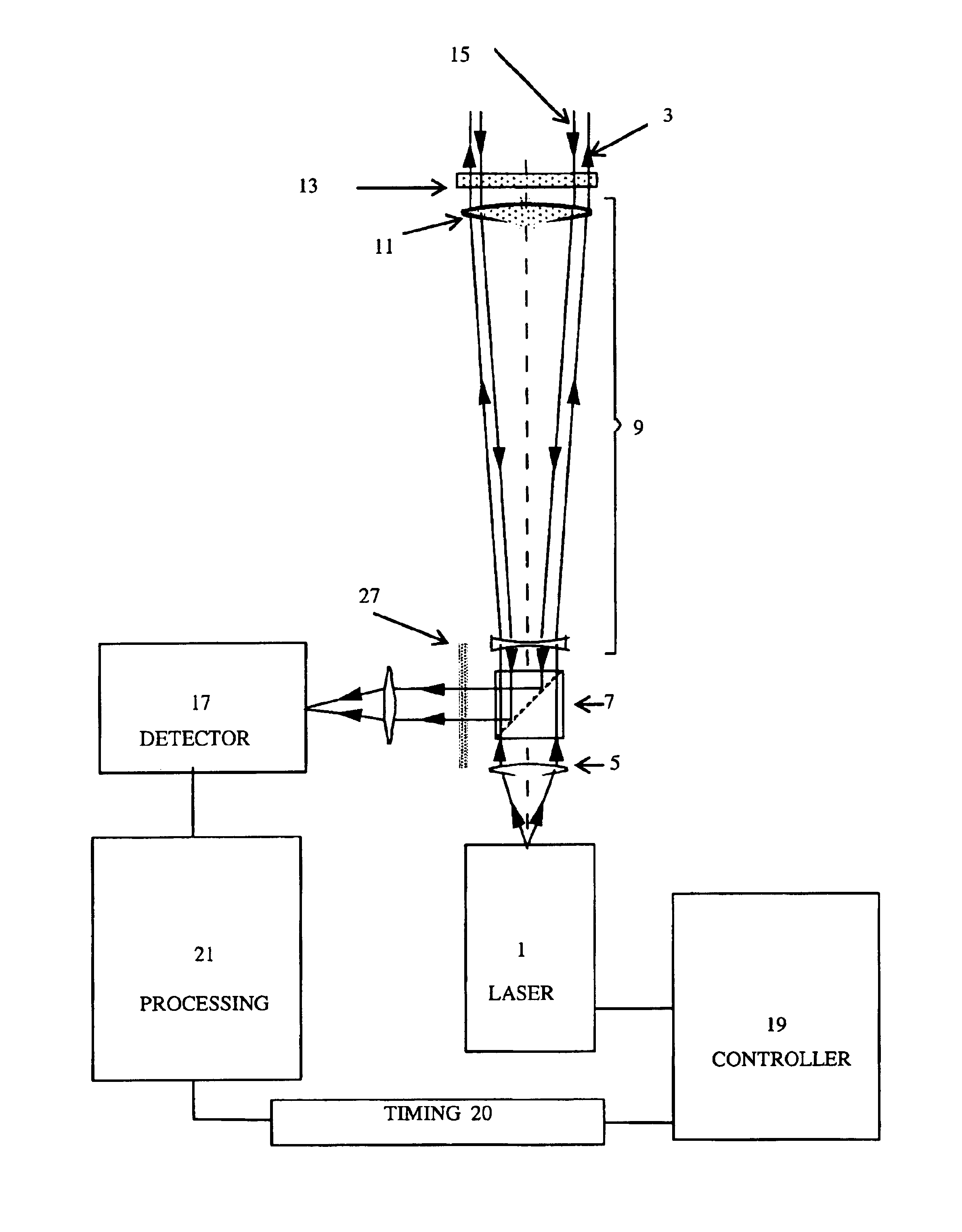
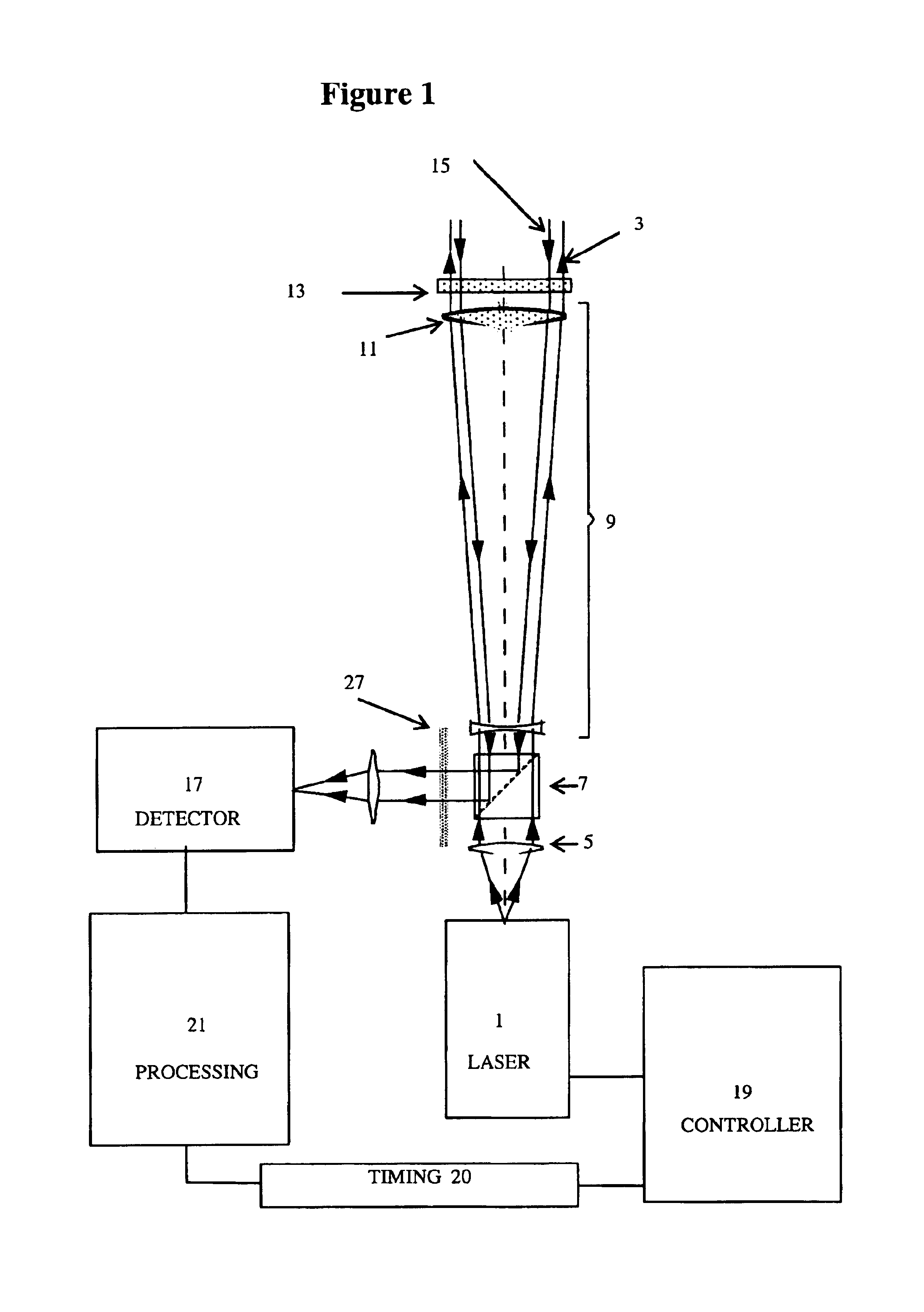
[0054]FIG. 1 shows an example of a “monostatic” configuration for the invention, i.e. a configuration in which there is a single optical system for both the probe beam output and the return beam collection. This monostatic configuration is the version of the invention tested and described in the later figures.

[0055]In FIG. 1, a semiconductor laser 1 emits 70 picosecond pulses at a repetition rate of 20 MHz and a power level of around 1 mW (The laser 1 used was a PicoQuant PDL 800 with a wavelength of 640 nanometres). The probe beam 3 produced by the laser 1 passes through a collimating lens 5 and then through a polarising beamsplitter 7. The polarised beam then passes through a telescope 9 and is collimated by the telescope's objective lens 11. Finally the beam passes through a quarter wave plate 13 before continuing onto the target (not shown).

[0056]The return signal 15 (which consists of reflected outward pulses) passes once again through the quarter wave plate 13. Thus the polari...


PUM


Abstract

An apparatus for detection and analysis of optical systems. Prior art systems exploit the phenomenon of photon scattering in order to range the distance of objects from the ranging apparatus. However, no information other than the distance of the target object is obtained from such systems. There is therefore provided an apparatus that exploits the technique of single photon counting and the phenomenon of retro reflection to provide information about a target optical system. Such information can be analysed and compared against known optical systems to provide a means of identification. Alternatively such information can be used as a method of quality control when constructing precision optical instruments such as telescopes or microscopes.

Description

[0001]The present application is a U.S. National Phase (371 application) of PCT / GB01 / 02756.BACKGROUND OF THE INVENTION[0002]1. Field of the Invention[0003]The present invention relates to an apparatus for optical detection and analysis and in particular an apparatus for identification of a selected optical system.[0004]Light beams will interact with any object in such a way that some energy will be diverted or converted. Depending on whether the object consists of refractive or reflective interfaces such interactive mechanisms will include scattering, reflection and refraction, all of which differ in efficiency within any given optical system depending on the light wavelength and the physical characteristics of the object.[0005]For example, the phenomenon of scattering is what underlies the operation of known optical range-finding systems such as a LIDAR (Light Distancing and Ranging), which is an optical equivalent of a RADAR system, or a Laser Range Finder system (LRF). In LIDAR / L...

Claims


Application Information

Patent Timeline
Patent Type & Authority Patents(United States)
IPC IPC(8): G01S7/48G01S7/497G01B11/00
CPCG01S7/4972
Inventor HAIG, NIGEL DOUGLAS
Owner QINETIQ LTD
Why Eureka
Try Eureka