Surge protected coaxial termination

a coaxial termination and surge protection technology, applied in the direction of emergency protective arrangements for limiting excess voltage/current, coupling device connection, waveguide type devices, etc., can solve the problems of loss of power transfer, interference with the signal, interference with the proper transmission of the desired radio frequency signal, etc., to avoid damage, capacitors can be relatively small and inexpensive, and the effect of controlling the characteristic impedance environmen

Inactive Publication Date: 2005-09-13
PPC BROADBAND INC
View PDF5 Cites 17 Cited by
  • Summary
  • Abstract
  • Description
  • Claims
  • Application Information

AI Technical Summary

Benefits of technology

[0022]As mentioned above, coaxial termination devices typically include a resistive component to absorb the RF signal, and prevent the reflection of the RF signal. Accordingly, the preferred embodiments of the present invention include a resistive terminating element electrically coupled between the center conductor and the metallic outer body. This resistor is electrically in parallel with the spark gap, whereby surge currents that jump the spark gap flow around the resistor, avoiding damage thereto. Accordingly, the resistor can be relatively compact and inexpensive.
[0023]As also mentioned above, coaxial termination devices typically include an AC / DC power blocking capacitor coupled in series with the resistor between the center conductor and the metallic outer body. Once again, the capacitor can be relatively small and inexpensive because the spark gap protects the capacitor from damaging high voltage power surges.
[0024]Another novel feature of the preferred form of the present invention relates to the manner by which such resistive and capacitive components of the coaxial termination device are incorporated therein. Preferably, the resistive component is disposed inside the metallic outer body, and extends co-axially with the center conductor. Ideally, this resistive component is formed inexpensively as a carbon composition resistor. The resistive component may be surrounded by, and supported by, dielectric material disposed inside the central bore of the metallic outer body, thereby maintaining the resistor in a controlled characteristic impedance environment. One end (electrode) of the resistive component is electrically coupled with an end of the center conductor. The opposing second end (electrode) of the resistive component may protrude from the metallic outer body and related dielectric material; the DC blocking capacitor preferably extends radially between the second end of the resistive component and the metallic outer body, or to a grounding post secured thereto. Since the DC blocking capacitor is surge-protected, it may be of a compact and inexpensive design, such as a chip capacitor.

Problems solved by technology

If such a coaxial termination is omitted, then undesired reflected signals interfere with the proper transmission of the desired radio frequency signal.
The resistor and capacitor of such known coaxial termination devices are often located outside the controlled characteristic impedance environment, creating an impedance mismatch that reflects some of the forward-transmitted signal back toward its source.
These reflections can result in loss of power transfer and interference with, or corruption of, the signal.
Accordingly, some signal degradation results from the use of such coaxial termination devices.
The degree of such signal degradation at a given frequency, resulting from such impedance mismatch, is sometimes expressed as the RF return loss performance of the coaxial system.
Moreover, when deployed in the field, as in cable TV systems, for example, these known coaxial termination devices can be subjected to power surges caused by lightening strikes and other events.
These power surges can damage or destroy the resistive and / or capacitive elements in such a termination, rendering it non-functional.
At least some of the known coaxial termination devices have difficulty complying with such surge test.
Indeed, efforts to make the resistive and capacitive components larger, in order to withstand such power surges, can have the negative impacts of increased costs and / or creating a larger impedance mismatch, and hence, causing poorer levels of RF Return Loss performance.
Unfortunately, such components are relatively expensive and have a much larger physical size, which tends to increase the size and cost of the housing necessary to contain such components, thereby resulting in a much bulkier and more costly design.

Method used


Image

  • Surge protected coaxial termination
  • Surge protected coaxial termination
  • Surge protected coaxial termination

Examples


Embodiment Construction

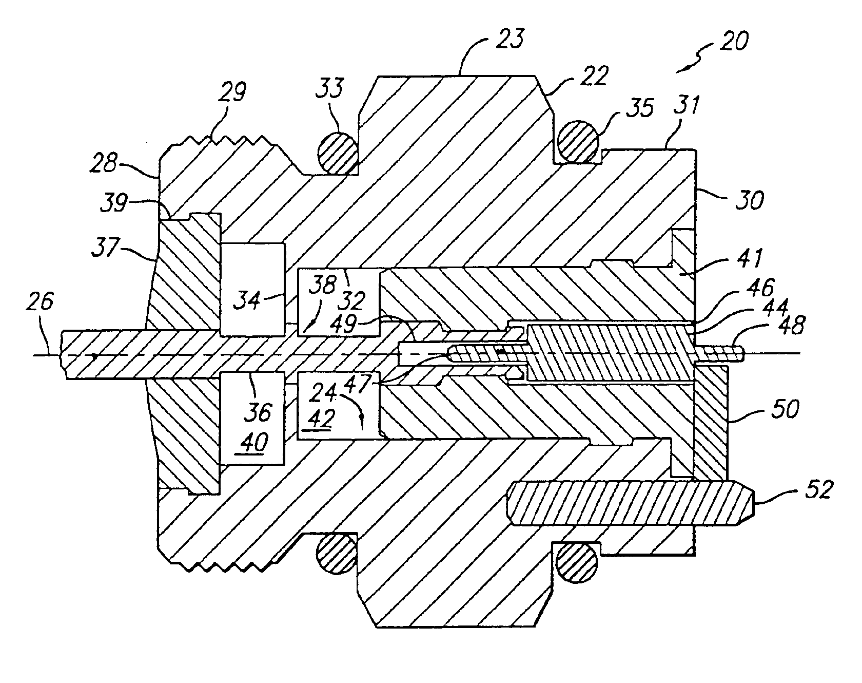
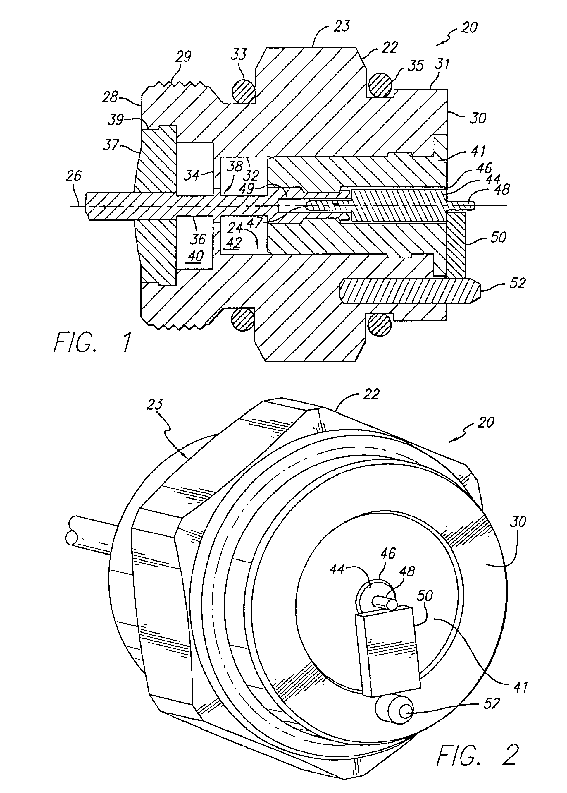
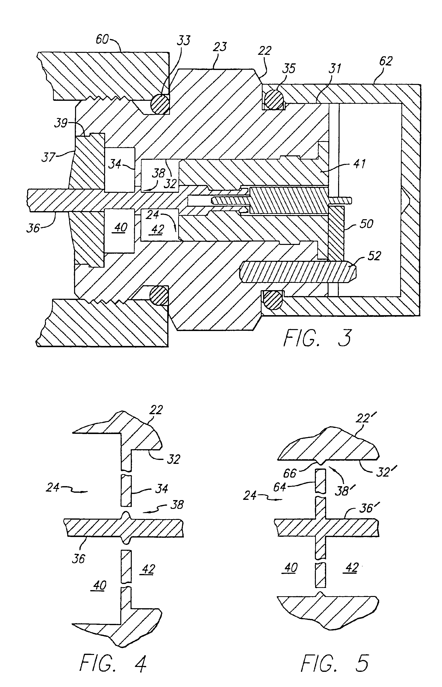
[0032]A surge-protected coaxial termination constructed in accordance with a preferred embodiment of the present invention is shown in FIGS. 1 and 2 and is identified generally therein by reference numeral 20. Coaxial termination device 20 includes a metallic outer body 22 incorporating a hex-shaped outer profile 23 for receiving the jaws of a wrench when coaxial termination device 20 is tightened onto a coaxial port of a transmission line equipment box. Metallic outer body 22 has a central bore 24, or central passage, extending therethrough along a longitudinal axis 26 between a first end 28 and a second end 30 of metallic outer body 22. Central bore 24 is bounded by an inner wall 32. As shown in FIG. 1, an inwardly-directed, radial step 34 extends from inner wall 32 toward central axis 26. This step 34 is relatively short in the sense that its length along central axis 26 is very short by comparison with the axial length of the remaining portion of inner wall 32. Likewise, the inn...


PUM


Abstract

A surge-protected coaxial termination includes a metallic outer body, a center conductor extending through a central bore of the outer body, and a spark gap created therebetween to discharge high-voltage power surges. A pair of dielectric support insulators support the center conductor on opposite sides of the spark gap. High impedance inductive zones surround the spark gap to form a T-network low pass filter that nullifies the additional capacitance of the spark gap. An axial, carbon composition resistor is disposed inside the outer body, and inside the dielectric insulator to absorb the RF signal, and prevent its reflection. The resistor extends co-axially with the center conductor, and one end of the resistor is electrically coupled thereto. A blocking chip capacitor extends radially from the opposite end of the resistor to the grounded outer body. The opposing second end of the resistive component may protrude from the metallic outer body and related dielectric material; the DC blocking capacitor preferably extends radially between the second end of the resistive component and the metallic outer body, or to a grounding post secured thereto.

Description

RELATED APPLICATION[0001]This application is a continuation application of U.S. patent application Ser. No. 09 / 712,433, filed Nov. 14, 2000 now U.S. Pat. No. 6,751,081, and the benefit of such earlier filing date is hereby claimed pursuant to 35 U.S.C. §120.BACKGROUND OF THE INVENTION[0002]1. Field of the Invention[0003]The present invention relates generally to coaxial terminations used to terminate ports that are adapted to receive coaxial cable connectors, and more particularly, to an improved coaxial termination that offers protection against high-voltage surges.[0004]2. Description of the Related Art[0005]RF coaxial cable systems are well known to those in the cable television industry for distributing radio frequency signals to subscribers of cable television service, and more recently, voice and data telecommunications services. The coaxial cables used to route such signals include a center conductor for transmitting a radio frequency signal, and a surrounding, grounded outer...

Claims


Application Information

Patent Timeline
Patent Type & Authority Patents(United States)
IPC IPC(8): H01P1/26H01T4/08H01P1/24H01T4/00H01R13/00H01R13/646H01R13/533H01R24/48H01T4/10H02H9/06
CPCH01P1/266H01R24/48H01T4/08H01R2103/00
Inventor KOOIMAN, JOHN A.
Owner PPC BROADBAND INC
Why Eureka
Try Eureka