Receiving apparatus and method for digital multi-carrier transmission

a transmission apparatus and multi-carrier technology, applied in the direction of signal generators with optical-mechanical scanning, color television with bandwidth reduction, television systems, etc., can solve the problem of reducing the transmission efficiency of the transmission, the manpower to out the carrier detection and symbol synchronization may not have been established, and the problem of improving the accuracy of the carrier detection

Inactive Publication Date: 2005-09-13
PANASONIC CORP
View PDF21 Cites 31 Cited by
  • Summary
  • Abstract
  • Description
  • Claims
  • Application Information

AI Technical Summary

Benefits of technology

[0011]The invention provides a receiving apparatus and method which can perform a carrier detection in a frequency domain in the DWMC transmission method.

Problems solved by technology

However, in the DWMC transmission method in which wavelet transform is used, the manner in which to out the carrier detection and the symbol synchronization may not have been established.
Accordingly, it may become problematic to improve the accuracy of the carrier detection and / or the symbol synchronization in the receiving apparatus.
In addition, it may also become problematic to suppress the degradation of transmission efficiency when the carrier detection and / or the symbol synchronization are / is carried out in the receiving apparatus.

Method used


Image

  • Receiving apparatus and method for digital multi-carrier transmission
  • Receiving apparatus and method for digital multi-carrier transmission
  • Receiving apparatus and method for digital multi-carrier transmission

Examples


first embodiment

(First Embodiment)

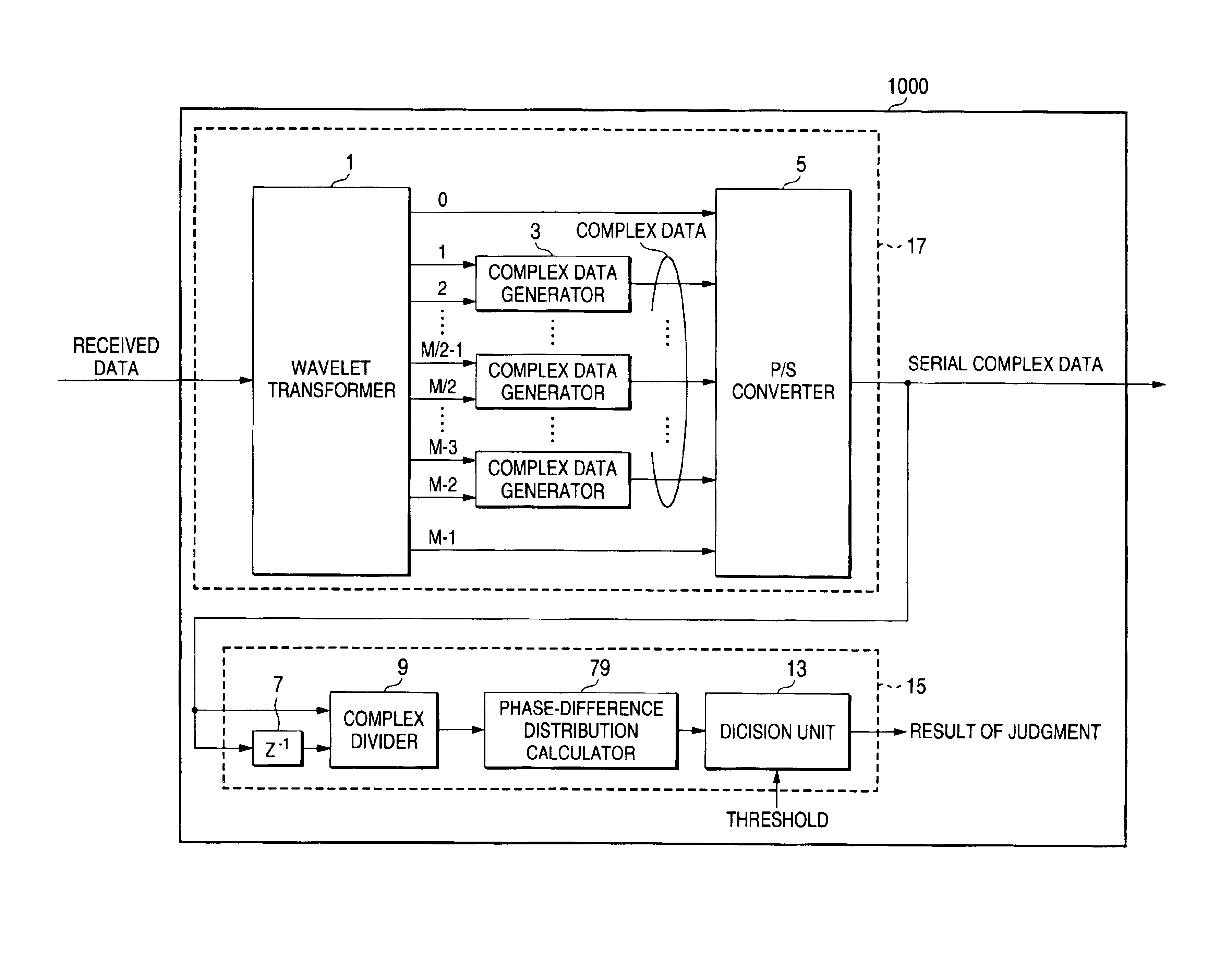
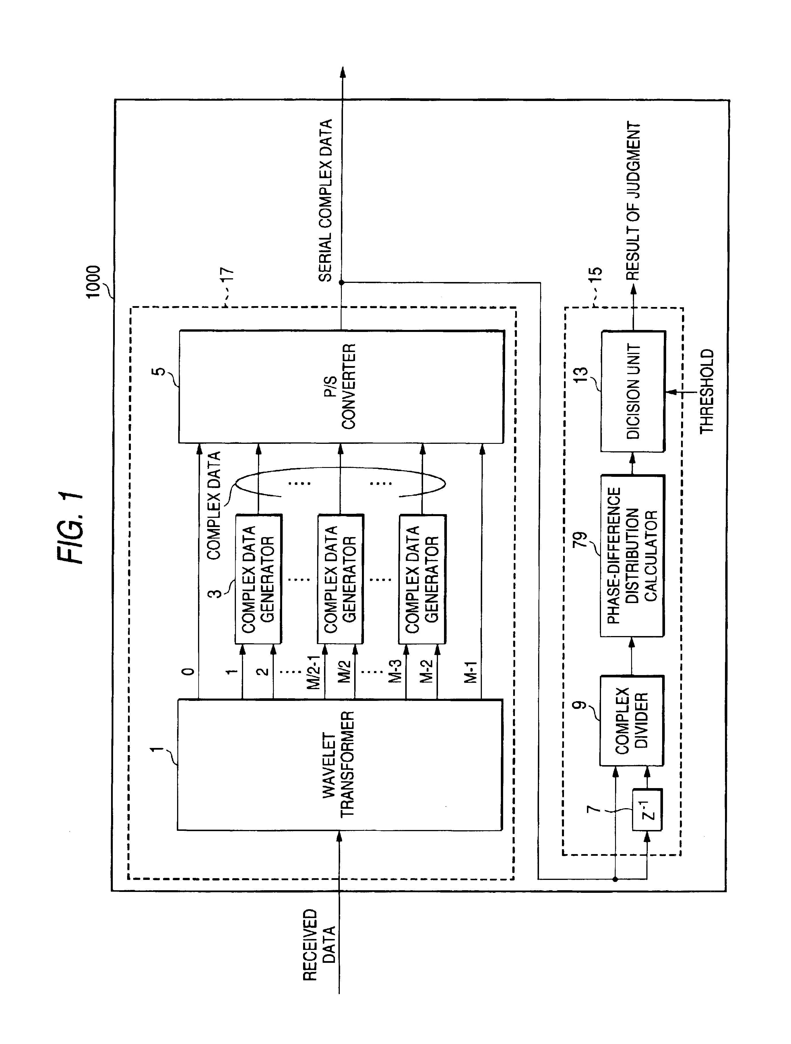
[0040]In FIG. 1, a receiving apparatus 1000 includes a carrier detector 15 and a wave detecting portion 17.

[0041]The wave detecting portion 17 includes a wavelet transformer 1, a complex data generators 3 and a parallel-to-serial (hereinafter P / S) converter 5. The wavelet transformer 1 is comprised of M real wavelet filters that are orthogonal to each other (M is a positive integer). The wavelet transformer 1 receives data, performs a wavelet transform to the received data, and then outputs M subcarriers (0 to M−1 in FIG. 1). The complex data generators 3 generate complex data from in-phase components (I channel) of the complex information and orthogonal components (Q channel) of the complex information: I channel are (2n−1)-th subcarriers from the wavelet transformer 1 and Q channel are 2n-th subcarriers from the wavelet transformer 1, wherein (1≦n≦M / 2−1). The complex data express complex subcarriers respectively. Moreover, the complex data generators 3 output the...

second embodiment

(Second Embodiment)

[0051]A receiving apparatus of the present embodiment has the same configurations with the receiving apparatus of the first embodiment except for the phase-difference distribution calculator. Accordingly, the phase-difference distribution calculator will be described in detail in the present embodiment.

[0052]As shown in FIG. 5, the phase-difference distributor calculator 39 (which is described as the phase-difference distributor calculator 11 in FIG. 1) includes a phase shifter 31, a sign decision unit 33, a counter 35, and a maximum value detector 37.

[0053]The phase shifter 31 shifts a phase of a part of the divided complex data received from the complex divider 9 by π / 4. The sign decision unit 33 decides the particular quadrant in which the divided complex data is located in accordance with a sign of each of the divided complex data. In this embodiment, there are two sign decision units 330 and 331. The counter 35 counts the number of the complex data in each of...

third embodiment

(Third Embodiment)

[0061]A receiving apparatus of the present embodiment also has the same configurations with the receiving apparatus of the first embodiment except for the phase-difference distribution calculator. Accordingly, the phase-difference distribution calculator will be described in detail in the present embodiment.

[0062]In FIG. 8, a phase-differential distribution calculator 53 includes a sign decision unit 51, a counter 36, and a maximal value detector 37. In this embodiment, there are two sign decision units 510 and 511, four counters 360 to 363 and the maximal value detector 37 in the phase-difference distribution calculator 53, respectively. The sign decision unit 510 receives an in-phase signal in the complex data, and the sign decision unit 511 receives an orthogonal signal in the complex data. Each of counters 360 to 363 counts each number of sign data output from the sign decision unit 510 and 511. The maximal value detector 37 compares the outputs from each of th...


PUM


Abstract

A receiving apparatus and method for performing carrier detection in a frequency domain for a digital wavelet multi-carrier transmission. A wavelet transform of received data is performed to output complex data and then the complex data is delayed for one sampling period. Subsequently, the delayed complex data and delayed complex data are divided. A number of the divided complex data present within each of plural quadrants on orthogonal coordinates is calculated and a maximum number of data present within one of the quadrants is selected and compared with a threshold in order to decide whether the received data is intended data.

Description

BACKGROUND OF THE INVENTION[0001]1. Field of the Invention[0002]The present invention relates to a receiving apparatus and method employing a multi-carrier transmission method utilizing real coefficient wavelet filter banks (Digital Wavelet Multi-Carrier transmission method, which is hereinafter called “DWMC transmission method”).[0003]2. Description of the Related Art[0004]The transmission method involving digital modulation and demodulation processes utilizing real coefficient wavelet filter banks is a type of multi-carrier modulation method in which a plurality of digital modulated waves are synthesized from real coefficient filter banks to generate a transmission signal. In the method, PAM (Pulse Amplitude Modulation) is used as a method for modulating each carrier.[0005]A data transmission method according to the DWMC transmission method will be described with reference to FIGS. 23 to 26.[0006]As shown in FIG. 23, each subcarrier has an impulse response, and impulse responses o...

Claims


Application Information

Patent Timeline
Patent Type & Authority Patents(United States)
IPC IPC(8): H04L27/26H04L27/00
CPCH04L27/0004H04L27/0014H04L27/2657H04L27/2662H04L27/2652H04L27/264H04L27/2642
Inventor KOGA, HISAOKODAMA, NOBUTAKAKONISHI, TAISUKE
Owner PANASONIC CORP
Why Eureka
Try Eureka