Air cylinder controller

Active Publication Date: 2005-09-13
MARSH BELLOFRAM CORP
View PDF3 Cites 27 Cited by
  • Summary
  • Abstract
  • Description
  • Claims
  • Application Information

AI Technical Summary

Benefits of technology

[0013]One advantage resides in reduced noise during damper operation.
[0014]Another advantage resides in more rapid transient response and reduced settling time for damper setting changes.
[0015]Yet ano

Problems solved by technology

A problem arises in that air cylinders and other pneumatic devices can exhibit hysteresis, pressure drift, frictional settling delays, and other operating non-linearities and non-regularities.
Moreover, the operating non-regularities depend upon the operating environment of the air cylinder or other pneumatic device.
Control of such pneumatic devices is di

Method used


Image

  • Air cylinder controller
  • Air cylinder controller
  • Air cylinder controller

Examples


Embodiment Construction

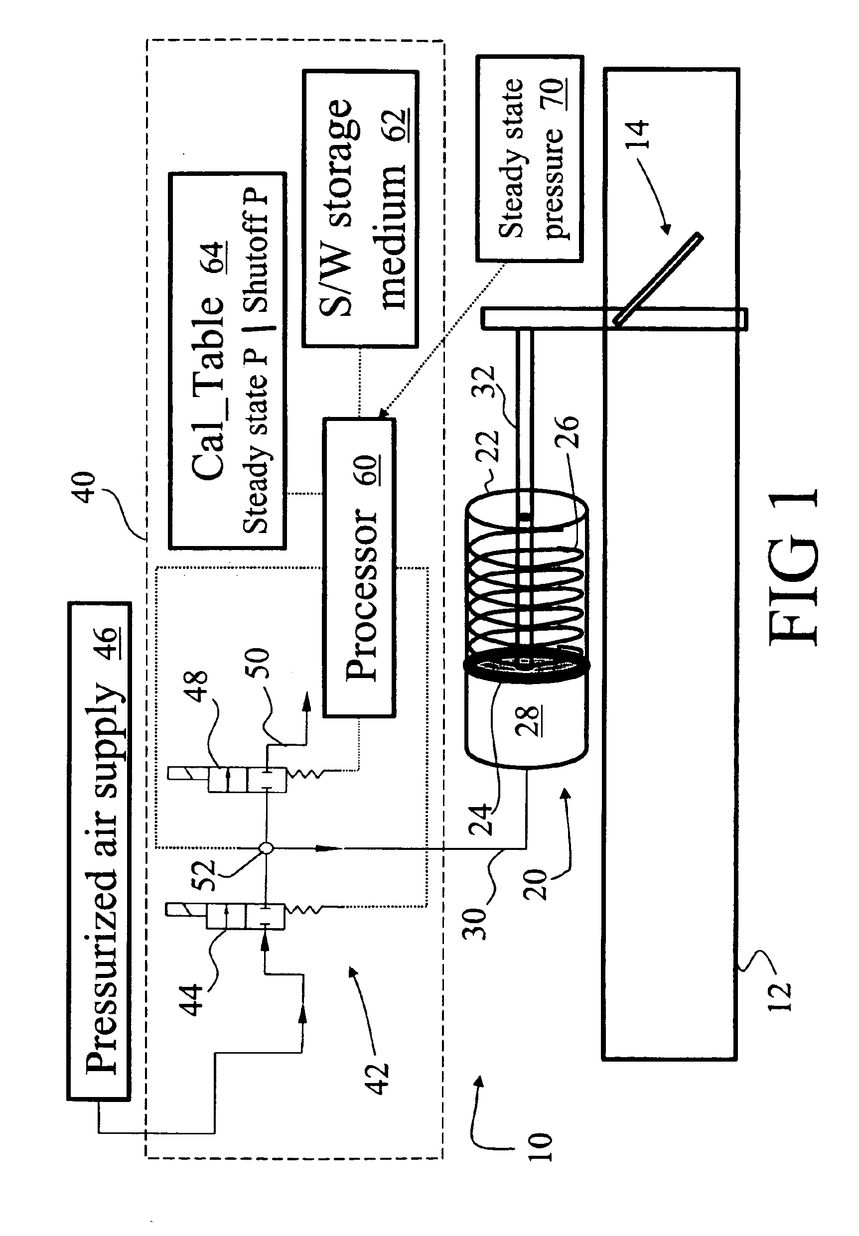
[0023]With reference to FIG. 1, a high volume air conditioning (HVAC) system 10 includes a plurality of ducts that convey heated, cooled or otherwise conditioned air throughout a building or other structure. In FIG. 1, the duct system is represented by exemplary duct 12. At selected places throughout the duct system, dampers are arranged to selectively control air flow. In FIG. 1, the various dampers are represented by an exemplary damper 14, which is a hinged damper. However, butterfly dampers, louvered dampers, or the like, and various combinations of such dampers, can also be employed. The HVAC system 10 typically further includes selected other components known in the art, such as a furnaces, flues, air conditioning units, particulate filters, registers, return air ducts, and the like, which are not shown in FIG. 1.

[0024]The damper 14 is moved by a pneumatic actuator, which in the exemplary embodiment of FIG. 1 is an air cylinder 20. The pneumatic air cylinder 20 includes a gene...


PUM


Abstract

An air flow regulator includes a damper (14) and an air cylinder (20) operatively connected with the damper (14) to adjust a damper setting. A pressure sensor (52) indicates a pneumatic pressure in the air cylinder (20). An air pressure regulator (42) is operatively connected with the air cylinder (20) to pressurize and exhaust the air cylinder (20) responsive to an electrical input (70). The air pressure regulator (42) includes a calibration table (64) associating steady state air cylinder pressure values with regulator shut-off pressure values. Responsive to the electrical input (70) updating a steady-state air cylinder pressure value, the air pressure regulator (42) pressurizes or exhausts the air cylinder (20) until the pressure sensor (52) indicates a pressure corresponding to a regulator shut-off pressure value associated in the calibration table (64) with the updated steady-state air cylinder pressure value, whereupon the air pressure regulator (42) ceases the pressurizing or exhausting.

Description

[0001]This application claims the benefit of U.S. Provisional Application Ser. No. 60 / 444,074, filed Jan. 31, 2003.BACKGROUND[0002]The present invention particularly relates to controlled operation of dampers in heating and air conditioning systems, especially high volume air conditioning (HVAC) systems, and will be described with particular reference thereto. The invention relates more generally to controlled operation of air cylinders and pneumatic / mechanical transducer systems, particularly for controlling fluid flow.[0003]In heating and air conditioning systems, conditioned air is distributed through a house, office building, or other structure through air ducts. Typically, the conditioned air is forced through a duct at a constant air speed, and control of the heating or cooling for a particular room or area of the house, office building, or other structure is effected by partially restricting air flow through a duct using one or more strategically placed dampers.[0004]The damp...

Claims


Application Information

Patent Timeline
IPC IPC(8): G05D16/18G05D16/20G05D16/00
CPCG05D16/2053G05D16/2093Y10T137/0396G05D16/2097
Inventor SHIER, WILLIAM W.THEUSCH, LEE H.SNAVLEY, JAMES D.
Owner MARSH BELLOFRAM CORP
Why Eureka
Try Eureka