Supercharge Your Innovation With Domain-Expert AI Agents!

Slave unit, node unit, controllers and network system

a network system and node technology, applied in the field of slave and node, processing unit and network power supply monitor system, can solve the problems of increasing the time to process communications, increasing the load of execution and processing of plc programs, and increasing the communication load between master and slav

Inactive Publication Date: 2005-09-13
ORMON CORP
View PDF9 Cites 7 Cited by
  • Summary
  • Abstract
  • Description
  • Claims
  • Application Information

AI Technical Summary

Benefits of technology

[0034]Hence, it is an object of the present invention to obtain the operating time of devices as service information without affecting the control system on the PLC side. Specifically, it also an object thereof to be able to precisely measure, on the slave side, time based on operations, such as operating time, waiting time, etc. of output and input devices connected to the slave.
[0042]In accordance with the two configurations described above, a slave itself is capable of measuring physical volume of itself or a control device and obtaining a measured value, with the measuring means. The measuring means is executed independently of processing of the control system that is performed by sending and receiving I / O data with the controller (master unit) via usual remote line. Therefore, effects on control can be suppressed as soon as possible. Also, non-limiting data (non I / O data) such as service information that is information based on a measured value measured with the measuring means can be noticed to a predetermined recipient, by reserving it at the slave and outputting it to a line (network) with predetermined timing. This enables the recipient to collect information based on the measured value.
[0060]And, on the precondition of each slave described above, it is better to comprise a means of storing and retaining setting information to identify normal range of the said output or input device, and of comparing the operating time obtained above with setting information described above. Since operating time can be determined with relatively good precision in accordance with the present invention, a comparison with setting:information makes it possible to judge whether or not the output or input device is normal, or whether time of replacement approaches, etc.
[0065]In accordance with this invention, by employing a timing means that is built-in on the slave or node side, time from when an operation of output device has started till output of an input device changes (output device will enter a predetermined state) is measured. Hence, time based on operating time of the output device can be determined correctly.

Problems solved by technology

However, when an attempt is made to obtain service information on the PLC side, as mentioned above, two problems will arise.
Firstly, load of execution and processing of a program of PLC will increase.
Secondly, communications load between a master and slave will increase.
Thus, volume of information to be communicated will expand, and cause to increase time to process communications, and a communications cycle between the master and slave will be long.
In addition, if the cable length is determined with a sufficient margin included, wiring may not be possible due to insufficient length of cables at a site where FA system is to be constructed.
Therefore, the associated work is not only very time-consuming but also complicated because a slave is sometimes installed on a back of the apparatus which is not easy to measure, etc.
In addition, there was no means of monitoring a voltage value of supply voltage at each slave.
This sometimes led to inconvenience that abnormal conditions could only be detected when communications with the slave is disabled due to voltage drop in operation.
Furthermore, if a power supply source of the device 5 is the Input / output device power supply apparatus 7, a problem similar to those mentioned above will occur.
For this reason, there was a problem that reliability of the system was degraded.
To carry out associated operation, however, PLC should make judgment on transmission of a message and reception of a response, which will cause a problem that inherent control of the device 5 will be affected.
However, execution of additional operations to determine the operating time described above while operations are cyclically processed on PLC unit 1 side for controlling the entire FA system will hamper high-speed control.
Moreover, another problem will be caused wherein as the number of devices to be processed grows, additional operations on the PLC side will increase because more operations will be needed to calculate the operating time on the PLC side.
In other words, as described above, the operating time will be determined by cyclically performing operations at PLC unit 1 every time, thereby leading to execution of wasteful operations.

Method used


Image

  • Slave unit, node unit, controllers and network system
  • Slave unit, node unit, controllers and network system
  • Slave unit, node unit, controllers and network system

Examples


second embodiment

[0133]FIG. 8 shows the present invention. In this embodiment, instead of Mix slave, OUT slave 20 and IN slave 21 are connected to the field network 12. And, by conducting peer-to-peer communications (inter-slave communications), ON / OFF information of desired OUT terminal is given from OUT slave 20 to IN slave 21 (usually, a slave to which the sensor 15 is connected).

[0134]Then, in the processing unit of MPU in IN slave 21, procedures similar to those shown in the flowchart of FIG. 6 are executed, wherein based on ON / OFF information of OUT terminal received from OUT slave 20, start time when the applicable OUT terminal turns ON and stop time when predetermined IN terminal turns ON are obtained, and not only operating time is determined from a difference between them, but also It is compared with set values, and comparison result is retained.

[0135]Further, data transmission from OUT slave 20 to IN slave 21 can be implemented, for example, by having IN slave 21 store and retain in adva...

third embodiment

[0155]FIG. 13 shows the present invention. In this embodiment, unlike respective embodiments and modifications described above, operating time of the apparatus (actuator 14) is to be obtained based on input signal from 2 input devices (sensors).

first embodiment

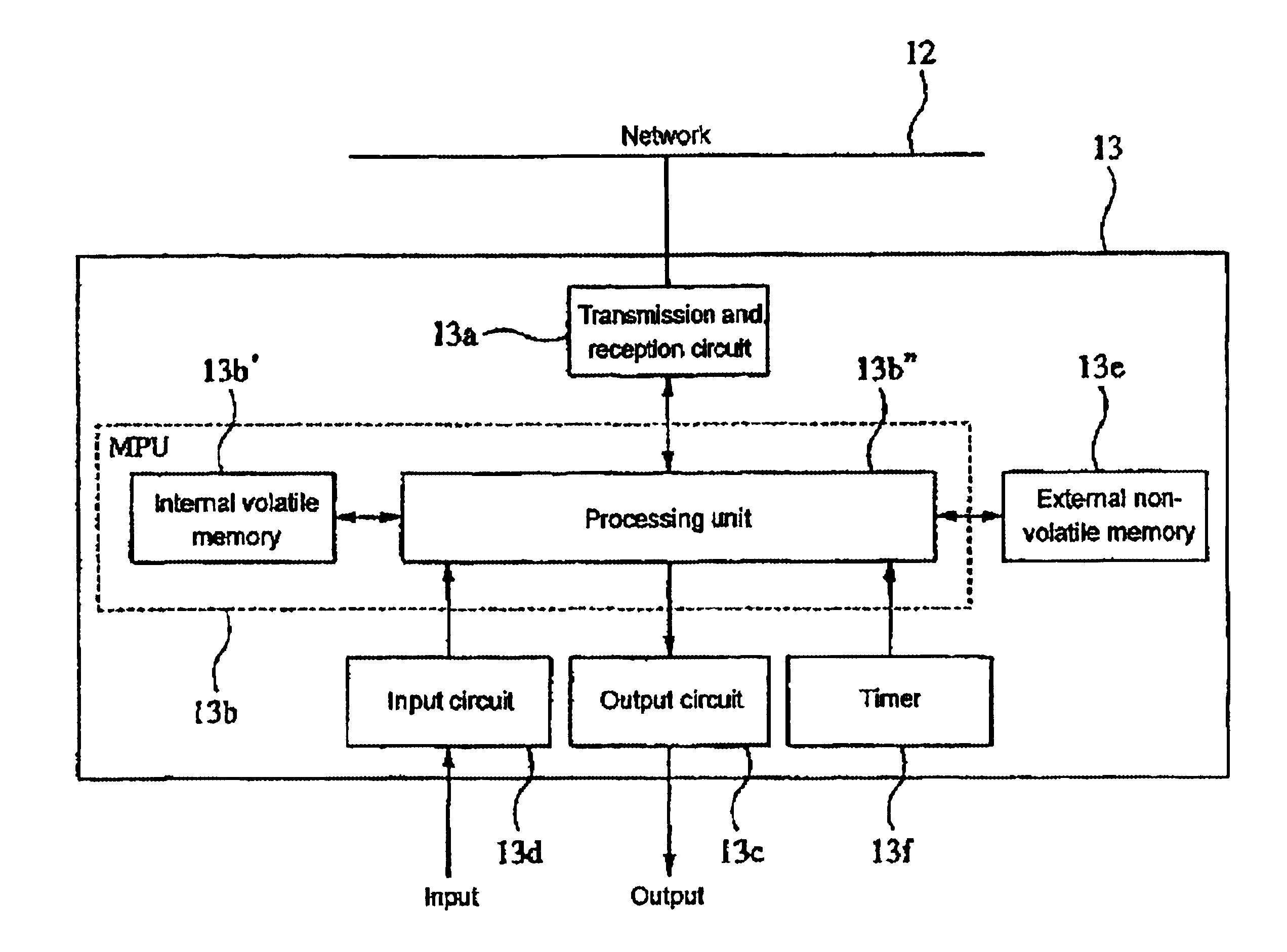
[0156]In other words, similar to the first embodiment, the actuator is connected to OUT terminal of Mix slave 13, and to IN terminal is connected the sensor that monitors a position of the mobile unit 14a of that actuator 14. However, in this embodiment, 2 sensors such as the first and second sensors 16a and 16b are prepared, as a sensor to be connected to IN terminal. And, the first and second sensors 16a and 16b are respectively located at X and Y, in the middle of the travel path (intermediate position) of the mobile unit 14a, whereby passage of the mobile unit 14a through the intermediate positions X and Y can be sensed. Further, the internal structure of Mix slave 13 is similar to that shown in FIG. 4.

[0157]According to this system, when OUT data turns ON, the mobile unit 14a of the actuator 14 begins to advance forward from the origin. Then, as shown in FIG. 14, as the mobile unit 14a reaches the intermediate position X, output of the first sensor 16a turns ON, and then turns ...


PUM


Abstract

Providing a slave that can precisely measure operating time of an output device that is service information, without having effects on a control system. To Mix slave 13 connected to a field network 12, an actuator 14 and sensor 15 that detects completion of operation of the actuator are connected. Having a built-in timer, the Mix slave measures time from when OUT terminal to which the actuator is connected turns ON until IN terminal to which the sensor is connected turns ON, by using the timer. Time thus obtained will be operating time of the output device. Comparison of this operating time with a setting will determine whether or not the actuator normally operates.

Description

BACKGROUND OF THE INVENTION[0001]1. Field of the Invention[0002]The present invention relates to a slave and node, and a processing unit and a network power supply monitor system, and an input / output device power supply monitoring system.[0003]2. Related Art[0004]As well known, in factory automation (hereafter referred to as “FA”), an I / O device is connected to a programmable controller (hereafter referred to as “PLC”) directly or via a network. A PLC is designed to control overall FA system by obtaining as Input data Information from such input devices as a switch or sensor that are a sort of the associated I / O devices, executing, in accordance with a pre-installed user program, an arithmetic operation with the associated input data obtained, to determine content of control to an output device that is a sort of the I / O device, and outputting control data corresponding to the control content, to such output devices as a valve or actuator, motor, etc.[0005]More specifically, control ...

Claims


Application Information

Patent Timeline
IPC IPC(8): G05B19/042G05B19/04G05B19/418G05B19/05H04L12/28
CPCG05B19/0423G05B19/4185G05B2219/21021G05B2219/21167G05B2219/23398G05B2219/25278Y02P90/02G05B19/05
Inventor UENO, SHINTAROIZUTANI, HAJIMESHIGEHISA, TOSHIYUKISHIMIZU, HIROSHIOCHI, NAOYA
Owner ORMON CORP
Features
  • R&D
  • Intellectual Property
  • Life Sciences
  • Materials
  • Tech Scout
  • Unparalleled Data Quality
  • Higher Quality Content
  • 60% Fewer Hallucinations
Learn More