Data flow control unit

Inactive Publication Date: 2005-09-13
ZOOM TELEPHONICS +1
View PDF22 Cites 5 Cited by
  • Summary
  • Abstract
  • Description
  • Claims
  • Application Information

AI Technical Summary

Benefits of technology

[0013]One way to sense the position of the key in the lock assembly is to couple the lock assembly to a switch and sense the state of the switch. Multiple switch positions, i.e., more than two, can be provided to support multiple access modes, where each position of the switch corresponds to a selected access mode and set of data flow rules that is to be used for regulating data flows. Different keys fitting the key-way of the lock assembly can be cut so that certain keys enable a key holder to set the switch to a limited number of positions, allowing a key-holder to select only certain access modes. Some keys can be cut so that a corresponding key-holder can turn the key in a corresponding lock assembly to select one of any of the possible access modes.
[0014]This aspect of the present invention is advantageous in applications where the communication link is coupled to a computer that is shared by multiple users. For example, each user can be issued a key enabling a corresponding user to select an appropriate access mode and retrieve information on a network.
[0015]In addition to limiting access to a network, the principles of the present invention can be used to block other types of data information. For example, an E-mail message directed to a target address on a network can be blocked from further transmission based upon a position of the key in the lock assembl

Problems solved by technology

This only adds to the difficulty of keeping track of a password at any given time.
Even if a password is written on a piece of paper for later reference, the paper can be easily lost or destroyed, thwarting its purpose.
Thus, if a hacker breaks into a computer system and retrieves a user's password, this key is easily passed on to other vandals who can then tamper with a computer sys

Method used


Image

  • Data flow control unit
  • Data flow control unit
  • Data flow control unit

Examples


Embodiment Construction

[0024]A description of preferred embodiments of the invention follows.

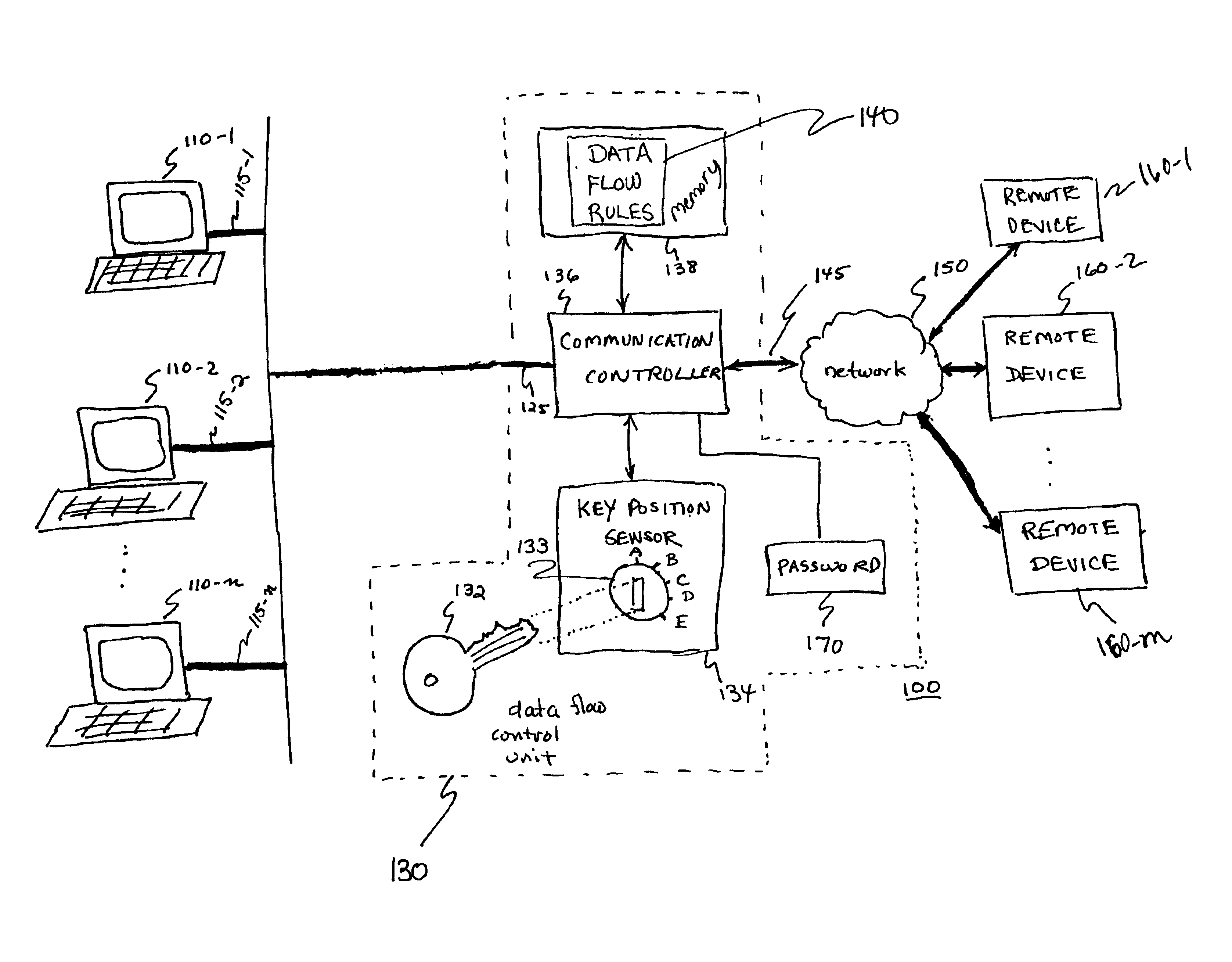
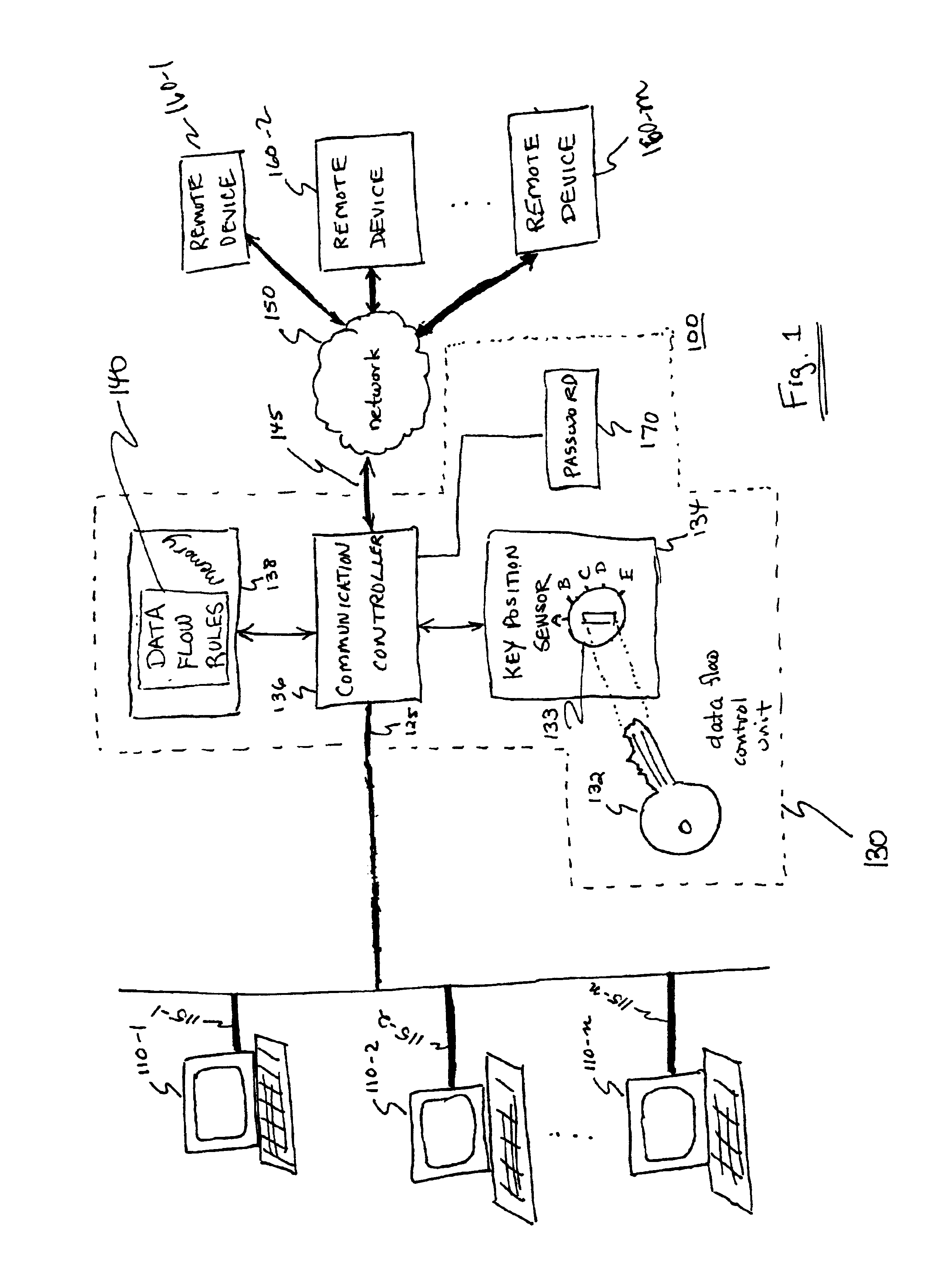
[0025]FIG. 1 is a block diagram of a communication system 100 incorporating a data flow control unit 130 for regulating a flow of data information through a data link according to the principles of the present invention. As shown, data flow control unit 130 is disposed to regulate a flow of data information between terminal equipment. For example, data information generated by a user at terminal device 110 is transmitted to a remote device 160. In a reverse direction, data information generated at remote device 160 is transmitted to any or all terminal devices 110-1, 110-2, . . . 110-n. Based on a position of key 132 in lock assembly 133, flows of data information are regulated. Thus, according to the principles of the present invention, a key-holder can control access of one or multiple users at corresponding terminal devices 110 by switching the key 132 in the lock assembly 133 to an enabling or disabling positi...


PUM


Abstract

An apparatus and method for regulating a flow of information based on a position of a key in a lock assembly is presented. Depending on a position of the key in the lock assembly and data flow rules, an electronic circuit regulates a flow of data to a target network. Data flow rules may be based on session type, transmit time, target address and password.

Description

RELATED APPLICATIONS[0001]This application is a continuation-in-part of and claims priority to U.S. application Ser. No. 09 / 595,152 filed Jun. 16, 2000, which itself claims the benefit of prior U.S. Provisional Application Ser. No. 60 / 139,986 filed on Jun. 18, 1999, entitled “Access Control Lock,” the entire teachings of both of which are incorporated herein by this reference.BACKGROUND[0002]Many computer-related applications incorporate some level of security to restrict user access. For example, in many applications, it is often necessary that a user of a computer provide a password to log on to a computer and corresponding network. The use of a password provided by a user affords at least some level of protection against intruders that would otherwise tamper with a computer and its contents.[0003]Although the use of a password can be advantageously incorporated in many applications, there are sometimes drawbacks associated with their use. For instance, a user can forget a passwor...

Claims


Application Information

Patent Timeline
IPC IPC(8): G06F21/00H04L29/06
CPCG06F21/85H04L63/105G06F2221/2113
Inventor ENGLISH, EDWARD D.WHITNEY, DANA B.ZELENY, ROLLANDBURKE, WILLIAM L.
Owner ZOOM TELEPHONICS
Why Eureka
Try Eureka