Multi-rate torsion bar independent suspension spring

a suspension spring and multi-rate technology, applied in the field of variable rate torsion bars, can solve the problem of allowing only a single spring rate, and achieve the effect of optimizing handling characteristics and increasing design flexibility

Inactive Publication Date: 2005-09-20
ARVINMERITOR TECH
View PDF7 Cites 18 Cited by
  • Summary
  • Abstract
  • Description
  • Claims
  • Application Information

AI Technical Summary

Benefits of technology

[0003]The present invention provides a torsion bar suspension assembly including a control arm supported by a frame. The torsion bar extends along a longitudinal axis having a first end portion connected to the control arm and a second end portion engaging the frame. A contact arm is connected to the torsion bar and is arranged between the first and second end portions. The contact arm is spaced from the frame in a first position and engages the frame in a second position. When the contact arm is spaced from the frame between the first and second positions, a first spring rate is provided. Once the contact arm engages the frame between second and third positions, a second spring rate is provided that is different from the first spring rate. In this manner, the multi-rate torsion spring provides the packaging advantages of conventional torsion bars while providing increased design flexibility and optimize handling characteristics.

Problems solved by technology

However, a drawback of torsion bars is that they typically permit only a single spring rate.

Method used


Image

  • Multi-rate torsion bar independent suspension spring
  • Multi-rate torsion bar independent suspension spring
  • Multi-rate torsion bar independent suspension spring

Examples


Embodiment Construction

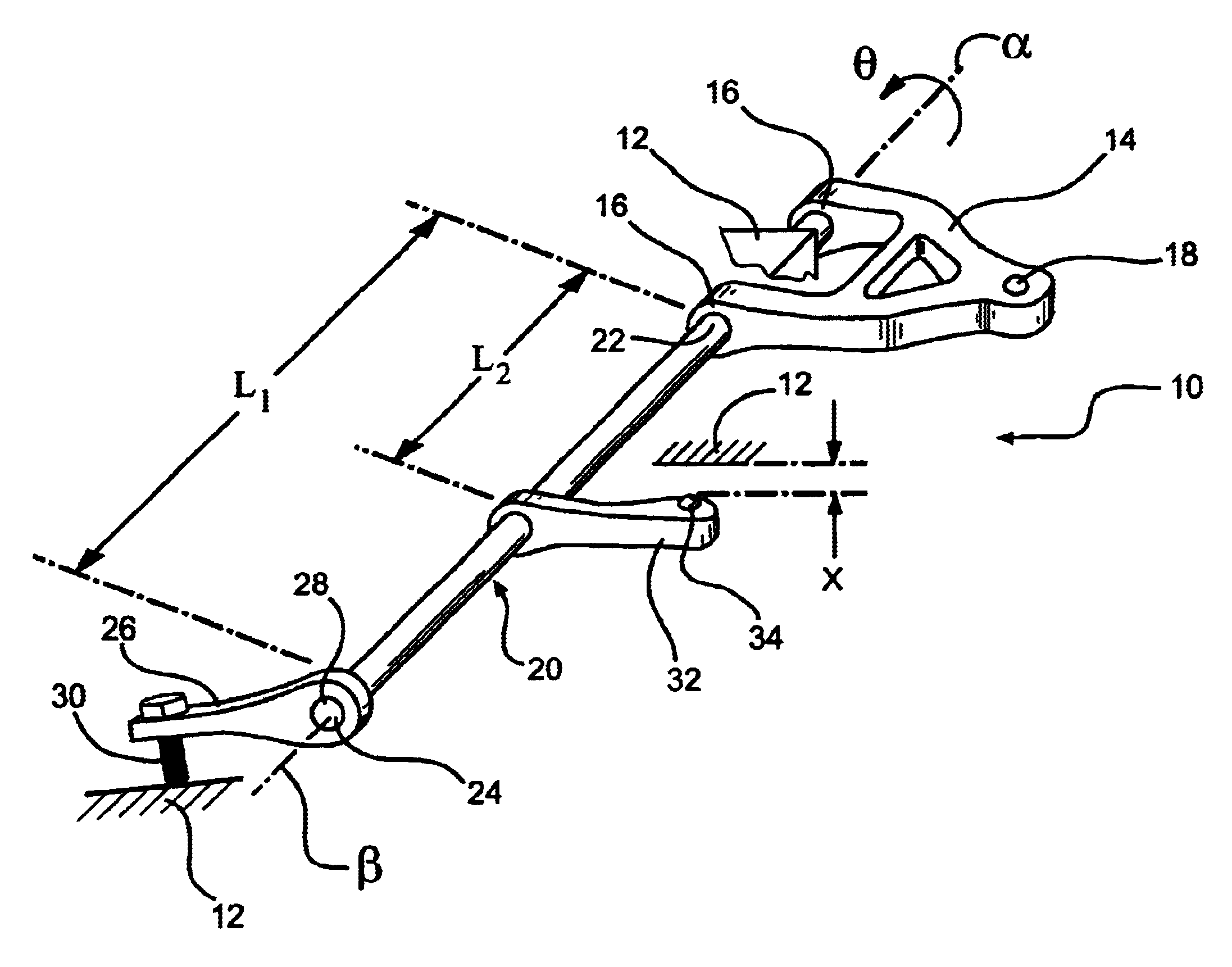
[0008]A torsion bar suspension assembly 10 is shown in FIG. 1. The assembly 10 includes a frame 12 rotationally supporting a control arm 14 at pivotal connections 16. The control arm rotates relative to the frame 12 about a rotational axis α. A wheel end assembly (not shown) is supported on the control arm 14 at a support connection 18. A coil spring (not shown) may be arranged between the control arm 14 and frame 12. The control arm 14 rotates an angle θ about the rotational axis α in response to inputs from the roadway.

[0009]A torsion bar 20 includes first 22 and second 24 end portions. The first end portion 22 is supported by the control arm 14. The torsion bar 20 has a longitudinal access β that is preferably coaxial with the rotational axis α. In the prior art, the second end portion 24 is directly supported by the frame. According to one aspect of the present invention, an adjustment arm 26 may be secured to a hexagonal end 28 of the second end portion 24. The adjustment arm 2...


PUM


Abstract

A torsion bar suspension assembly is provided that includes a control arm supported by a frame. The torsion bar extends along a longitudinal axis having a first end portion connected to the control arm and a second end portion engaging the frame. A contact arm is connected to the torsion bar and is arranged between the first and second end portions. The contact arm is spaced from the frame in a first position and engages the frame in a second position. A first spring rate is provided when the contact arm is spaced from the frame between the first and second positions. Once the contact arm engages the frame between second and third positions, a second spring rate is provided that is different from the first spring rate.

Description

BACKGROUND OF THE INVENTION[0001]This invention relates to torsion bars for independent suspensions, and more particularly, the invention relates to variable rate torsion bars.[0002]Vehicle suspension assemblies may utilize torsion bars to increase the stiffness of the suspension and improve handling characteristics. For example, independent suspension that utilize coil springs frequently use torsion bars to provide supplemental stiffness to the coil spring at a different spring rate. Specifically, the torsion bar may be connected between a control arm and the frame. As the control arm moves vertically in response to inputs from the roadway, the torsion bar will rotationally deflect. Independent suspensions utilizing torsion bars can provide a significant packing advantage. However, a drawback of torsion bars is that they typically permit only a single spring rate. Multiple spring rates are desireable to provide refined handling characteristics. That is, it is desireable to provide ...

Claims


Application Information

Patent Timeline
Patent Type & Authority Patents(United States)
IPC IPC(8): B60G11/18B60G11/00B60G17/02
CPCB60G11/181B60G17/025B60G2202/132B60G2204/122B60G2204/43B60G2204/45B60G2204/61B60G2204/62B60G2206/427B60G2500/20
Inventor ESHELMAN, EDWARD JAY
Owner ARVINMERITOR TECH
Why Eureka
Try Eureka