LED planar light source and low-profile headlight constructed therewith

Inactive Publication Date: 2005-09-20
GE LIGHTING SOLUTIONS LLC
View PDF12 Cites 166 Cited by
  • Summary
  • Abstract
  • Description
  • Claims
  • Application Information

AI Technical Summary

Benefits of technology

[0011]According to still yet another aspect of the present invention, a method is provided for manufacturing a light source. A light emitting semiconductor die is secured to a reflective planar surface. An encapsulant is

Problems solved by technology

They are large, particularly in the vertical direction, which degrades aerodynamic performance and aesthetic qualities of vehicles.
This increases headlight cost.
When a sealed beam headlight fails for any reason, the entire sealed beam unit must be replaced.
These headlights permit replacement of the failed lamp without replacing the optics, but increase a likelihood of headlight misalignment due to the additional detachable lamp connection.
Another disadvantage of incandescent halogen or discharge lamps is limit

Method used


Image

  • LED planar light source and low-profile headlight constructed therewith
  • LED planar light source and low-profile headlight constructed therewith
  • LED planar light source and low-profile headlight constructed therewith

Examples


Embodiment Construction

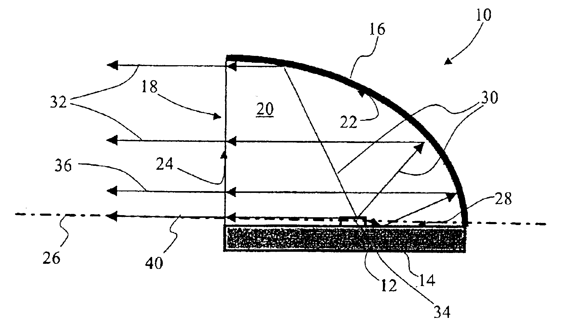
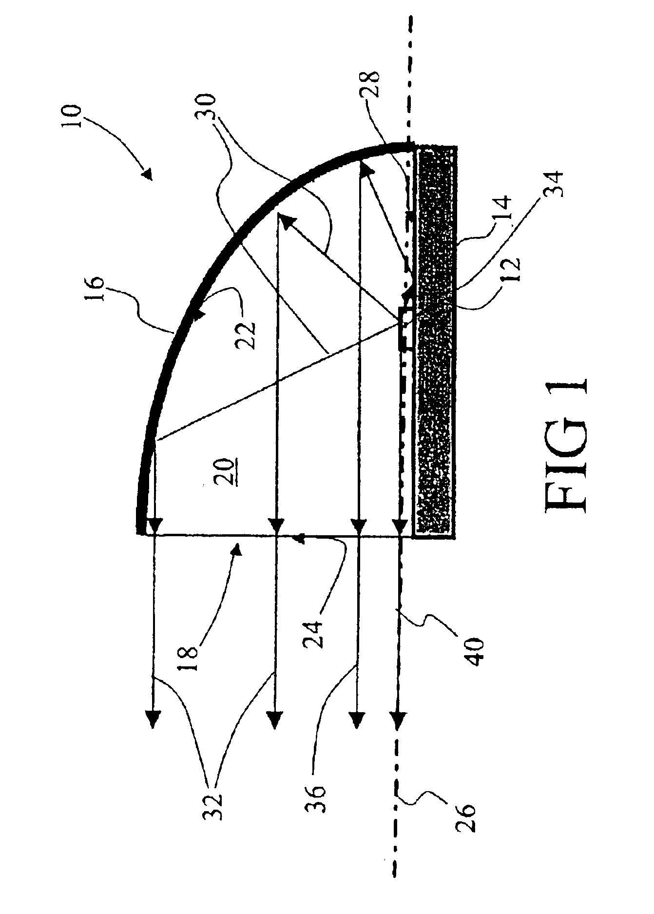
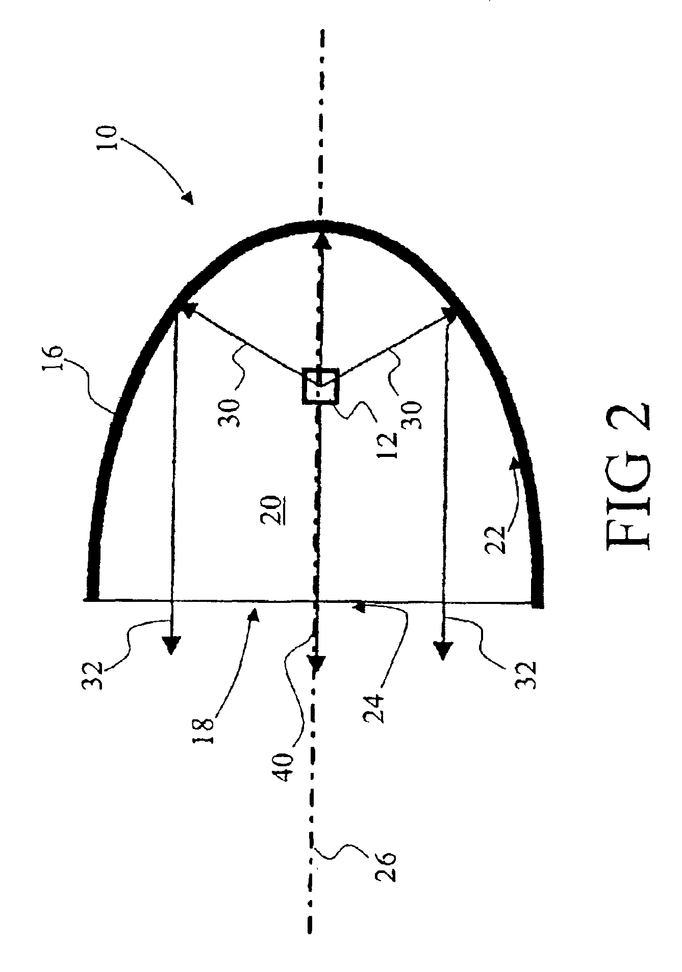
[0025]With reference to FIGS. 1 and 2, a light source 10 includes a light emitting semiconductor device 12 supported by a reflective support substrate 14. Typically, the semiconductor device 12 is a semiconductor die cut from a wafer and attached to the support substrate 14 by soldering, epoxy adhesion, or another method. Optionally, the semiconductor device 12 and the support substrate 14 are monolithically integrated, i.e. the support substrate 14 is a polished semiconductor substrate on which the light emitting semiconductor device 12 is fabricated using a selected combination of epitaxial crystal growth, photolithography, impurity diffusion, metal deposition, and / or other semiconductor processing techniques. In the monolithic embodiment, the semiconductor substrate is optionally coated with a metal to increase its reflectivity.

[0026]Preferably, the reflective support substrate 14 includes a primary heat sinking path for the light emitting semiconductor device 12. The substrate 1...


PUM


Abstract

A light source (10) includes a light emitting semiconductor device (12). A support substrate (14) has a generally planar reflective surface (28) that supports the semiconductor device (12). The light emitting semiconductor device heat sinks via the support substrate. A curved reflector (16) has a concave parabolic reflective surface. The light emitting semiconductor device (12) is arranged between the support substrate (14) and the curved reflector (16). The support substrate (14) and the curved reflector (16) together define a light aperture (18) through which light produced by the light emitting semiconductor device (12) passes.

Description

BACKGROUND OF INVENTION[0001]The present invention relates to the lighting arts. It especially relates to a rugged solid-state plane wave light source for producing a substantially plane wave light beam that is suitable for vehicle headlights and other applications, and will be described with particular reference thereto. However, the invention will also provide solid-state light sources producing other types of light distributions, such as light that is focused in one dimension and planar in an orthogonal dimension, plane wave light that is angularly tilted, and the like, for use in downlighting and other applications throughout the lighting arts.[0002]Present vehicular headlights typically employ filament-based light sources such as halogen lamps, or high-intensity discharge lamps that produce electric arc illumination by electrical discharge between electrodes in a high-pressure gas ambient. Such light sources produce a generally point source of light, which is collected and dire...

Claims


Application Information

Patent Timeline
IPC IPC(8): F21V29/00F21S8/10H01L33/00F21S8/02F21S8/04F21V7/00F21V7/06F21V7/09F21V13/02F21V31/04F21Y101/02H01L33/54H01L33/60H01S5/022
CPCF21S8/02F21S8/04F21S48/1159F21S48/328F21V7/0091F21V29/004F21V29/2212F21V31/04H01L33/60F21S10/06F21W2101/02F21W2111/00F21Y2101/02H01L33/54F21Y2115/10F21S45/47F21W2107/10F21V29/70F21S41/148G03B21/2026
Inventor DU, SHAWN X.HSING CHEN, MICHAEL C.SOULES, THOMAS F.DORNAUER, FRANK P.STIMAC, TOMISLAV J.SCHINDLER, ROBERT
Owner GE LIGHTING SOLUTIONS LLC
Why Eureka
Try Eureka