Turbine blade platform cooling system

a cooling system and turbine blade technology, applied in machines/engines, mechanical equipment, liquid fuel engines, etc., can solve the problems of low thermal stress on such components, and achieve the effects of reducing temperature and stress, improving the fatigue life of turbine blades, and facilitating coolant flow

Inactive Publication Date: 2005-09-20
SIEMENS ENERGY INC
View PDF22 Cites 66 Cited by
  • Summary
  • Abstract
  • Description
  • Claims
  • Application Information

AI Technical Summary

Benefits of technology

[0003]Thus, one object according to aspects of the present invention is to improve the fatigue life of turbines blades by reducing temperature and stress in the platform. Another object according to aspects of the present invention is to configure a blade platform so as to facilitate coolant flow while also reducing the structural stiffness of the platform. One more object according to aspects of the invention is to use impingement cooling to substantially evenly reduce metal temperatures and thermal gradients in the blade platform. An additional object according to the invention is to employ the pressure differentials existing between various portions of the blade so as to induce cooling flow. Still another object according to aspects of the present invention is to provide a blade platform having an integrated cooling system so as to avoid the need for additional parts and / or subsequent assembly steps. A further object according to aspects of the present invention is to provide cooling to the leading and trailing edge sides of the platform. Objects according to aspects of the present invention also relate to a method for cooling a turbine blade platform.

Problems solved by technology

Various components in the turbine section of a turbine engine, including the rotating turbine blades, are subjected to extremely high temperatures, which can impart thermal stresses on such components.
Exposure to high temperatures and thermal stresses can result in the turbine blades having low fatigue lives, which commonly manifest as cracks in the blade platform.

Method used


Image

  • Turbine blade platform cooling system
  • Turbine blade platform cooling system
  • Turbine blade platform cooling system

Examples


Embodiment Construction

[0020]Aspects of the present invention improve upon prior systems for cooling the platform of a turbine blade. Aspects of the present invention relate to a turbine blade assembly having a platform configured to improve fatigue life of the turbine blade by cooling the platform while also reducing thermal stresses on the platform.

[0021]Embodiments of the invention will be explained in the context of one possible turbine blade assembly, but the detailed description is intended only as exemplary. Embodiments of the invention are shown in FIGS. 1-9, but the present invention is not limited to the illustrated structure or application.

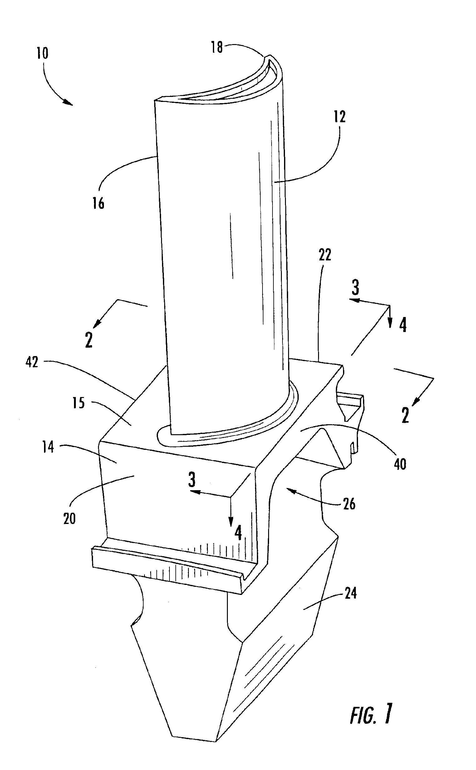
[0022]One example of a turbine blade assembly 10 is shown in FIG. 1. The turbine blade assembly 10 can include an airfoil portion 12 extending radially away from a platform portion 14. The platform portion can be generally planar, cylindrical or otherwise curved. The airfoil portion 12 can have a leading edge 16 and a trailing edge 18. The leading edge 16 is ...


PUM


Abstract

Aspects of the invention relate to a cooling system for a blade platform that can provide cooling to and reduce stress on the platform. Aspects of the invention relate to including one or more channels in the blade platform such that the channels extend from the trailing edge face of the platform toward, but terminate prior to, the leading edge face of the platform. The channels can be generally oval or oblong in conformation. Extending between the hollow shank and the channels can be a plurality of cooling holes. During engine operation, coolant is supplied to the shank of the blade assembly. Because the pressure at the shank is greater than the pressure at the trailing edge of the platform, coolant flow is induced through the cooling holes and into the channels. After flowing through the channels, the coolant can be dumped at the trailing edge.

Description

FIELD OF THE INVENTION[0001]The invention relates in general to turbine engines and, more particularly, to a system for cooling the platform of a turbine blade.BACKGROUND OF THE INVENTION[0002]Various components in the turbine section of a turbine engine, including the rotating turbine blades, are subjected to extremely high temperatures, which can impart thermal stresses on such components. With respect to turbine blades, thermal stress is a function of temperature gradients as well as the structural stiffness of the blade. Exposure to high temperatures and thermal stresses can result in the turbine blades having low fatigue lives, which commonly manifest as cracks in the blade platform.SUMMARY OF THE INVENTION[0003]Thus, one object according to aspects of the present invention is to improve the fatigue life of turbines blades by reducing temperature and stress in the platform. Another object according to aspects of the present invention is to configure a blade platform so as to fa...

Claims


Application Information

Patent Timeline
Patent Type & Authority Patents(United States)
IPC IPC(8): F01D5/18F01D5/02F01D5/08
CPCF01D5/081F01D5/187F05B2240/33F05B2240/801F05D2240/122F05D2240/304F05D2240/81
Inventor DE CARDENAS, RAFAEL
Owner SIEMENS ENERGY INC
Why Eureka
Try Eureka