
Environment adaptable measurement endoscope

a technology of endoscope and environment, applied in the field of endoscope, can solve the problems of excessive complexity and troublesome operation of re-measurement, inability to specify the measurement environment, and time-consuming steps involving the measurement settings or parameters, so as to improve operability and prevent measurement

Inactive Publication Date: 2005-09-20
EVIDENT CORP
View PDF8 Cites 34 Cited by
  • Summary
  • Abstract
  • Description
  • Claims
  • Application Information

AI Technical Summary

Benefits of technology

[0018]Accordingly, it is one object of the present invention to provide an endoscope capable of preventing measurement under erroneous measurement environment assumptions, upon re-measurement using a recorded measurement image. Re-measurement is promptly performed without considering the measurement environment. Operability is improved by simply performing the re-measurement under the correct testing environment.
[0019]It is another object of the present invention to provide a measurement processing method (measurement software) capable of improving the operating efficiency of examination by re-measurement of the image recorded by the endoscope on a PC.
[0020]It is another object of the present invention to provide a measurement processing method capable of preventing measurement under an erroneous testing environment upon using a PC. In this manner, the measurement environment is suitably set to images recorded under various testing environments. Re-measurement is promptly performed without considering the environment. Operability is improved by simply performing the re-measurement under the correct testing environment.

Problems solved by technology

That is, in all cases, elaborate and time-consuming steps involving the measuring settings or parameters are necessary.
However, since the conventional apparatuses have no means for recording data indicating under which testing environment the image is photographed in the measured images, there is a danger that upon re-measurements using the same image for a while, the measurement environment cannot be set again or the measurement environment is set by erroneous connection of the devices for purpose of re-measurement because an operator forgets the measurement environment upon photographing the image.
The data on the measurement environment set to in the conventional apparatuses is limited to data on an arbitrary measurement environment and, therefore, when the re-measurement is performed by the image that is not suitable to the data on the measurement environment in the measurement endoscope apparatus such as a measurement image using the different type of optical adaptor, all the devices must be connected to the apparatus before actual re-measurement and the measurement environment must manually be performed again.
Thus, the operation for re-measurement is excessively complicated and troublesome.
However, since neither means nor processing for setting the testing environment on the PC exists, the re-measurement of the image captured to the PC cannot be performed.

Method used


Image

  • Environment adaptable measurement endoscope
  • Environment adaptable measurement endoscope
  • Environment adaptable measurement endoscope

Examples


first embodiment

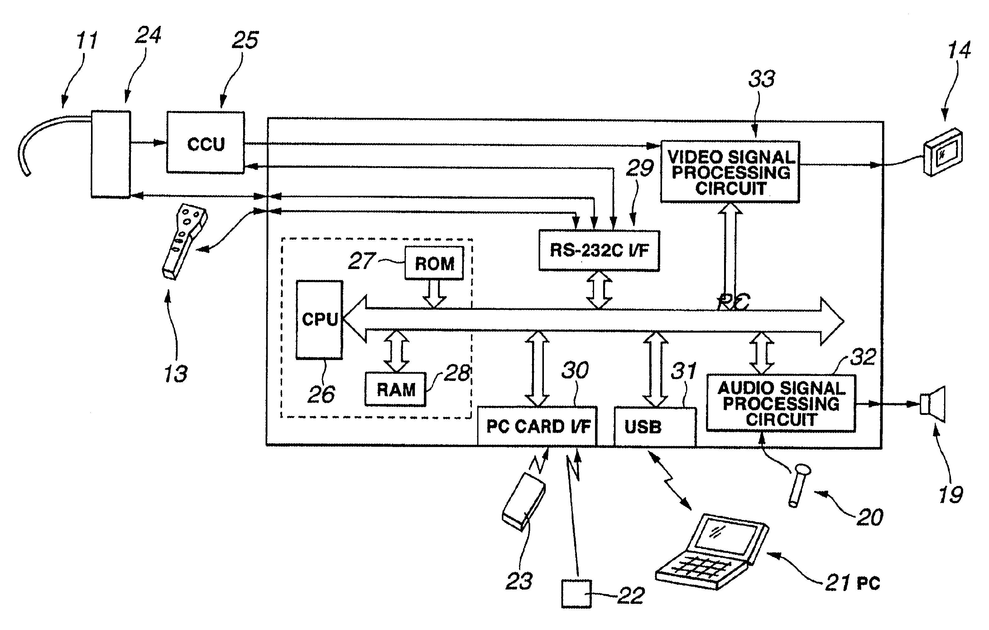
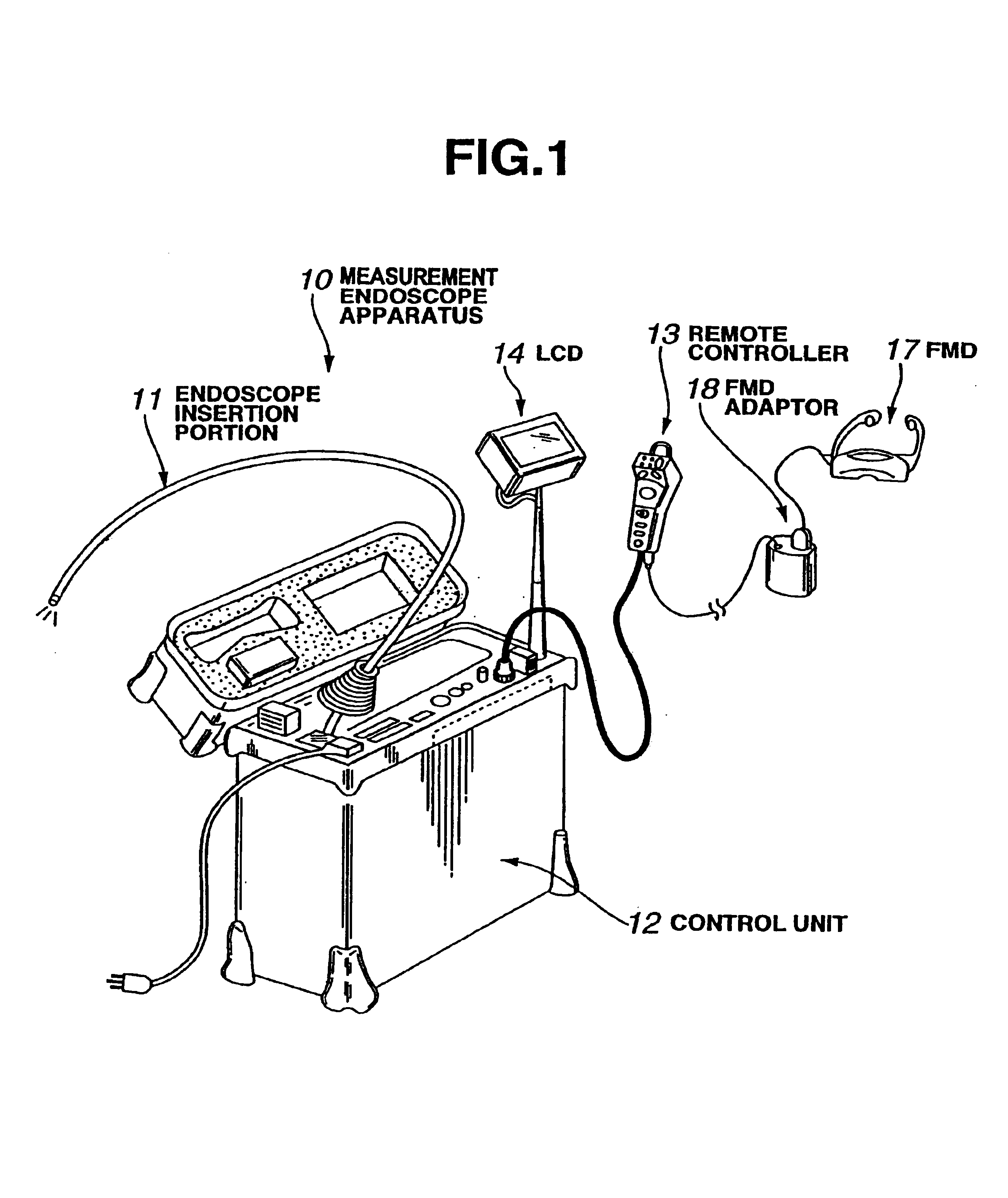
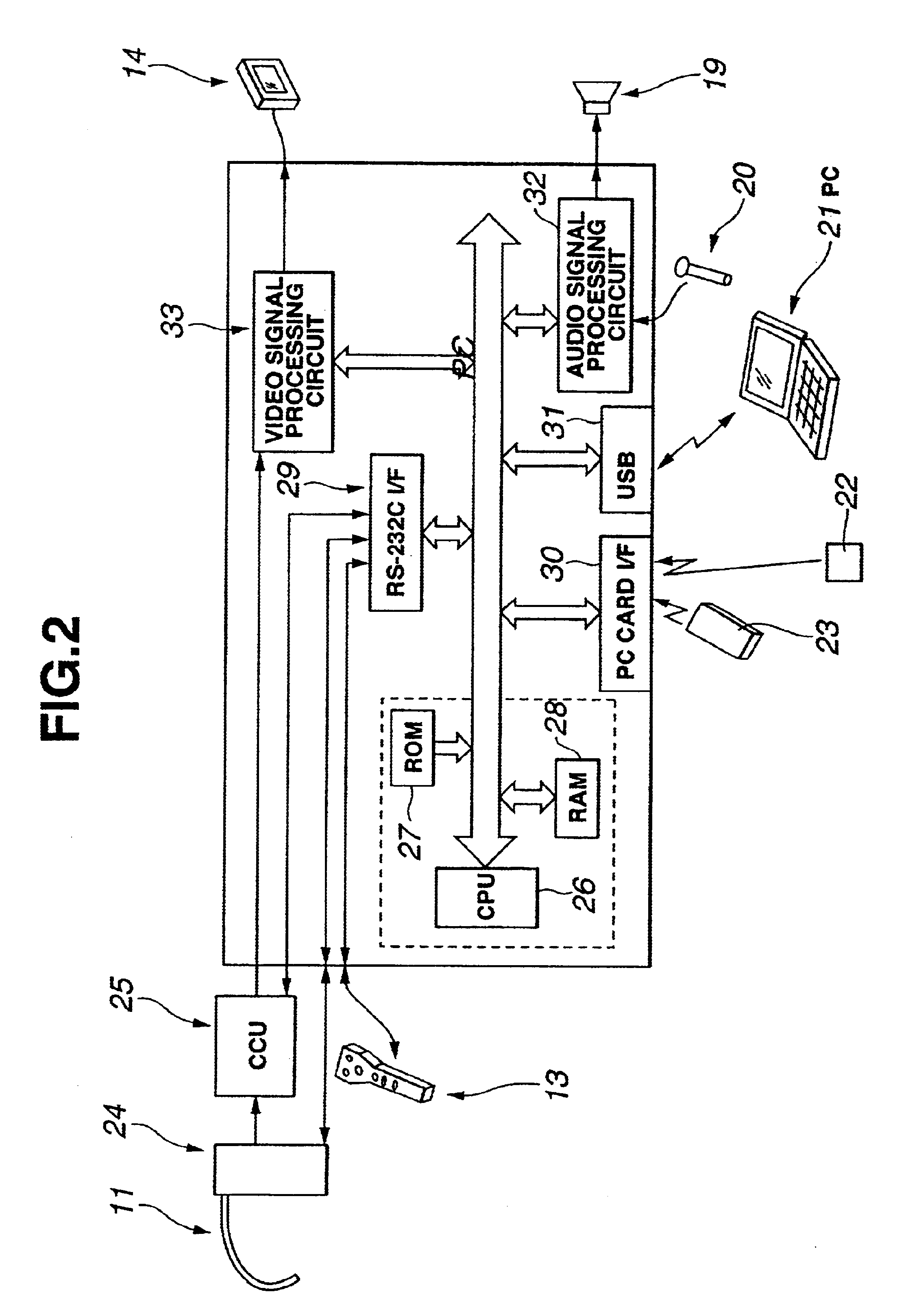
[0052]FIGS. 1 to 14B relate to the present invention. FIG. 1 is a perspective view showing the system structure of a measurement endoscope. FIG. 2 is a block diagram showing the structure of circuitry of the measurement endoscope apparatus illustrated in FIG. 1. FIG. 3 is a perspective view showing the structure of a remote controller illustrated in FIG. 1. FIG. 4 is a perspective view showing the structure of a tip portion of an endoscope insertion portion illustrated in FIG. 1. The tip portion is adapted to attach to a stereo measurement adaptor. FIG. 5 is a cross-sectional view of a V—V cut-line of the illustration of FIG. 4. FIG. 6 shows an endoscope image when attaching the stereo measurement adaptor illustrated in FIG. 4. FIG. 7 shows a mask-shaped image of the stereo measurement adaptor illustrated in FIG. 4. FIG. 8 shows a relationship between an original image and a corrected image for explaining the setting of a measurement environment in the endoscope illustrated in FIG. ...

second embodiment

[0166]Next, a description is given of a endoscope according to the present invention with reference to FIGS. 15A and 15B.

[0167]FIGS. 15A and 15B are flowcharts showing examples of the control operation by a CPU in the endoscope, as a feature, according to the second embodiment.

[0168]The structure according to the second embodiment is substantially the same as that according to the first embodiment. Therefore, only different points are described, the same components are designated by the same reference numerals, and a description thereof is omitted.

[0169]According to the second embodiment, when neither the information on the measurement environment nor the calibration data is recorded to the image recorded to the recording medium, the program executed according to the first embodiment is improved and an additional function is provided for the program so as to promptly execute the appropriate measurement.

[0170]Specifically, the recorded stereo measurement image is selected and the mea...

third embodiment

[0190]Next, a description is given of a endoscope according to the present invention with reference to FIGS. 16A and 16B.

[0191]FIGS. 16A and 16B are flowcharts showing the control operation by a CPU in a endoscope as a feature according to the third embodiment.

[0192]The third embodiment is substantially the same as the first embodiment. Therefore, only different points are described and the same reference numerals denote the same components. A description of the same components is omitted.

[0193]According to the third embodiment, the contents of the information positional relationship of the attachment of the optical adaptor included in the calibration data added to the image are compared with the contents of the information on the positional information included in the data on the measurement environment which has already been registered. Then, when the difference is larger than a predetermined threshold, processing for measurement using the calibration data added to the image is ad...


PUM


Abstract

A measurement endoscope system includes: an image pick-up device, an endoscope insertion portion to which a plurality of stereo measurement optical adaptors and a normal measurement adaptor are detachably attachable, a control unit for accommodating the endoscope insertion portion, a face mounted display for stereoscopically viewing a normal endoscope image or stereoscopically viewing the endoscope image as a pseudo stereo image, and the like. The control unit includes a CPU for controlling the execution of various functions based on a main program, a ROM, a RAM, a PC card, a USB port, an RS-232 port, an audio signal processing circuit, and a video signal processing circuit. The control unit can be connected externally to a PC. The measurement endoscope system allows taking image re-measurements under a correct measurement environment simple operation, with the re-measurements being performed promptly without consideration of the measurement environment. Thus, the operability of the system is improved and greatly expedited.

Description

RELATED APPLICATIONS[0001]This application claims benefit of Japanese Applications No. 2001-264847 filed in Japan on Aug. 31, 2001 and 2001-264849 filed in Japan on Aug. 31, 2001, the contents of which are incorporated by this reference.FIELD OF THE INVENTION[0002]The present invention relates to an endoscope for forming two images of a subject on an image pick-up device of an endoscope main body via a pair of objective lenses at different positions, and for performing the measurement or examination by image processing using the obtained endoscope images. The invention further relates to a measurement processing method (measurement software) for handling a measurement image recorded by the above-mentioned endoscope apparatus on a personal computer (hereinafter, referred to as a PC).BACKGROUND INFORMATION[0003]In general, detailed examination of a subject using an endoscope requires setting up the subject for being examined. To satisfy this requirement, conventionally, various measur...

Claims


Application Information

Patent Timeline
Patent Type & Authority Patents(United States)
IPC IPC(8): A61B1/00
CPCA61B1/00022A61B1/00039A61B1/00041A61B1/00048A61B1/0005A61B1/00055A61B1/00096A61B1/00101A61B1/00193A61B1/00108A61B2560/0431A61B1/0004A61B1/00042
Inventor YOKOTA, MASAYOSHI
Owner EVIDENT CORP
Learn More