
Steerable catheter

a technology of a steerable catheter and a lumen body, which is applied in the direction of multi-lumen catheters, catheters, other medical devices, etc., can solve the problems of inability to use, inconvenient use, and inability to use,

Inactive Publication Date: 2005-09-20
MEDTRONIC INC
View PDF29 Cites 331 Cited by
  • Summary
  • Abstract
  • Description
  • Claims
  • Application Information

AI Technical Summary

Benefits of technology

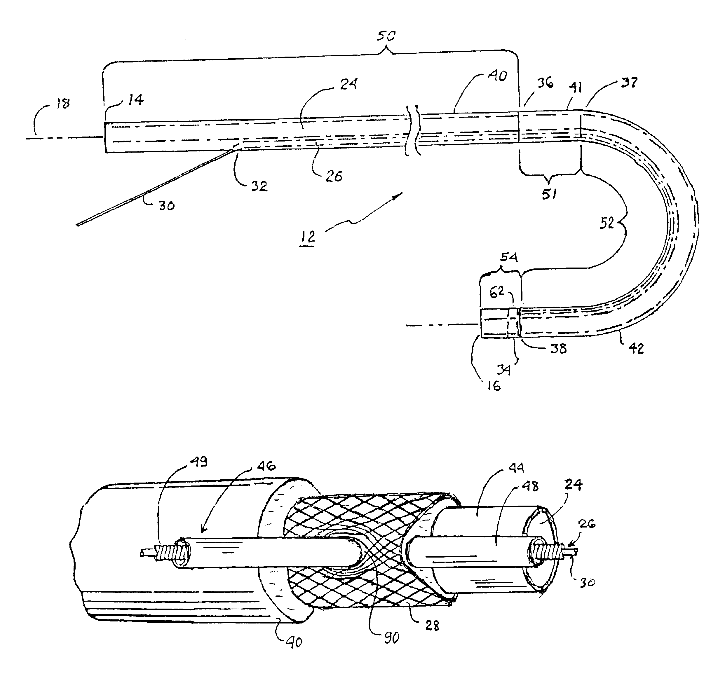
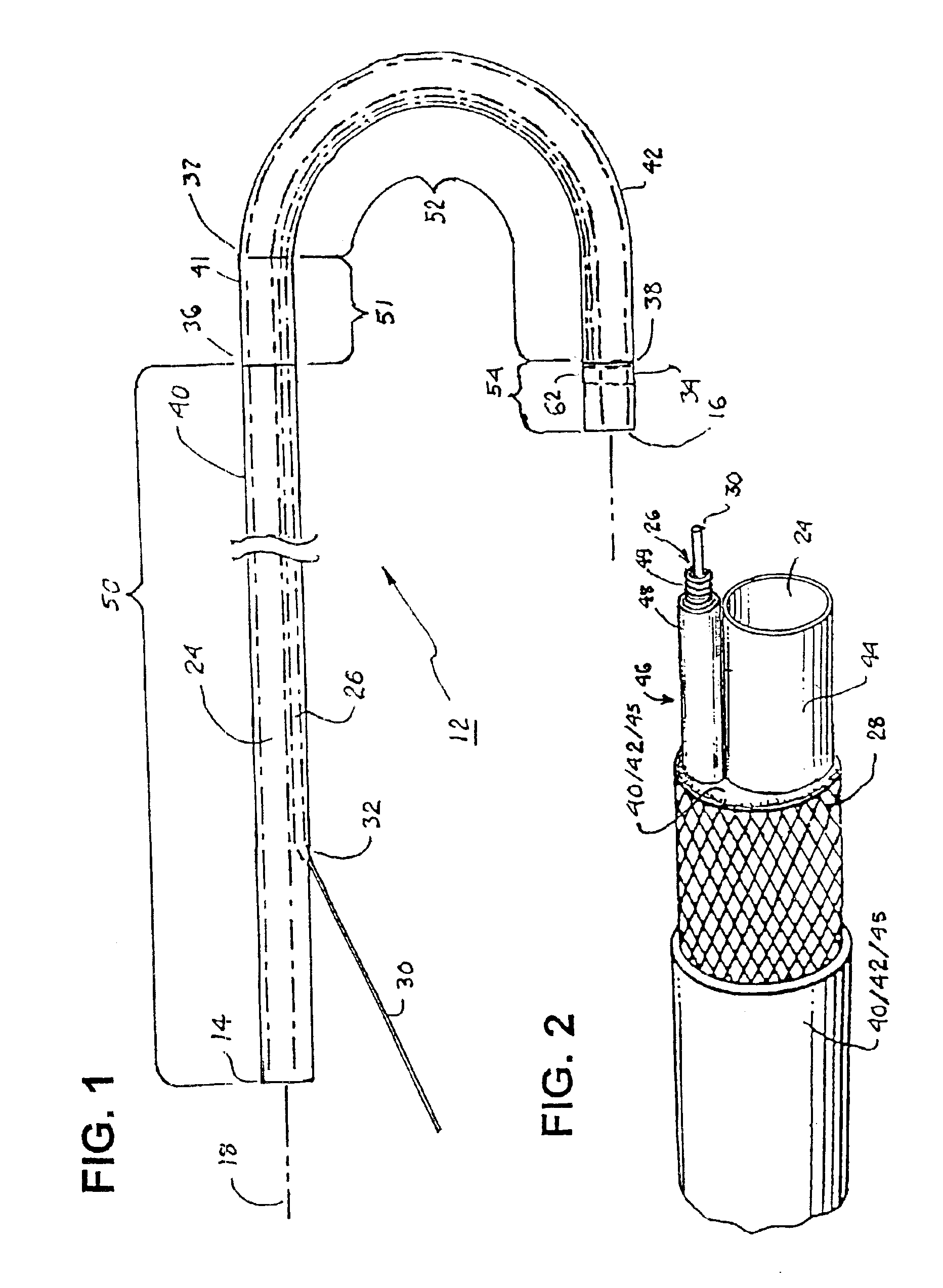
[0018]In a second aspect of the invention, a high tensile strength wire is employed to form the wire braid woven about the pull wire lumen liner and / or the delivery lumen liner that is entrapped mechanically at the catheter body distal end. Torqueability of the catheter body through the entire wire braid reinforced catheter body length is not negatively affected by annealing the wire braid during the fabrication process, since annealing is not necessary. More particularly, a band attached to the pull wire distal end is fitted over a distal segment of the wire braid and adhered with the wire braid prior to formation of the outer jacket of the catheter body. The band therefore entraps and prevents the wires at the distal end segment of the wire braid from flaring away from the delivery lumen liner and secures the pull wire distal end to the catheter body. The band is preferably radiopaque to provide a marker band visible under fluoroscopy.
[0019]In this way, the wire-braided sub-assembly is formed of the delivery lumen liner and the pull wire lumen liner tightly wound together in the distal segment with the wire braid thereby avoiding the need to anneal the wire ends, minimizing manual handling of the parts, minimizing the diameter of the wire-braided sub-assembly and avoiding bunching of the wire braid and twisting of the wire braid and / or the lumen liners, and resulting in a uniform sub-assembly that is readily testable for defects. Moreover, the braid port is prepared through the wire braid that the proximal segment of the pull wire lumen liner extends through, eliminating the need to dissect through the wire braid to access the pull wire lumen.
[0021]In a particular embodiment of the invention, the pull wire lumen liner is formed of a wire coil disposed within the lumen of a pull wire lumen sheath. Preferably, the wire coil turns are closely wound except for a distal segment corresponding in length with the length of the distal segment of the catheter body adapted to be bent into a curved shape by tensioning the pull wire where the wire coil turns are space wound. The uniform diameter and the hard surface of the wire coil lumen facilitate the insertion of the pull wire through its length and out of the braid port.
[0022]In a further aspect of the invention, the sub-assembly is encapsulated in a reflow encapsulation process to form a polymeric outer sheath reinforced by the wire braid and embedding the delivery lumen liner and the distal segment of the delivery lumen liner. The delivery lumen mandrel remains in the delivery lumen and the pull wire remains in the pull wire lumen during encapsulation of the sub-assembly to form the outer jacket. In this way, the pull wire is already present during the encapsulation. It is not necessary to remove a separate pull wire lumen mandrel from the encapsulation to form the pull wire lumen, and it is not necessary to later insert the pull wire into the pull wire lumen.
[0024]Advantageously, holes can be made through the sidewalls of the thermoplastic jacket and the overlying heat shrink tube that are to be positioned to overlie the braid port and that are large enough so that the pull wire lumen liner and the pull wire within the pull wire lumen can be inserted through the aligned sidewall holes before reflow melting of the thermoplastic jacket. Mistakes in making the sidewall holes simply result in scrapping the inexpensive jacket and heat shrink tube. Moreover, the sidewall holes can be preformed in an automated assembly. This avoids the potential leakage problems attendant to the prior art practice of cutting through the outer jacket to locate the pull wire lumen.
[0026]Further steps are taken to place a thermoplastic intermediate jacket and a thermoplastic transition jacket (located between the proximal and intermediate jackets) within the elongated heat shrink tube lumen. Heat is then applied to shrink the heat shrink tube and melt the thermoplastic proximal, transition and intermediate jackets within the heat shrink tube lumen in a reflow encapsulation process. The melted thermoplastic polymers flow through the wire braid and around the pull wire lumen and / or delivery lumen liners. The pull wire lumen sheath of the pull wire lumen liner prevents flow of melted polymer into the wire coil defining the pull wire lumen. A further reflow process is employed to melt a distal jacket of thermoplastic material and encapsulate the distal radiopaque band and distal section of the delivery lumen liner. When the encapsulation is completed, the pull wire lumen sheath and wire coil can be cut away carefully at the pull wire jacket port to expose a proximal length of the pull wire.

Problems solved by technology

Other steerable catheters are more complex, typically incorporating one or more distal electrode and corresponding conductor, and sometimes including other sensors, inflatable balloons, and other components.
Therefore extrusion techniques used to fabricate relatively large diameter, thick walled, multi-lumen fluid drainage or hemodialysis catheters and early steerable catheters, e.g., that are disclosed in the above-referenced '725 patent, are inappropriate.
In the context of use of the steerable catheter body in a cautery or an EP catheter, the leakage of saline into the handle can short out electrical connections therein and / or present a risk of electrical shock to the user if the saline is in contact with the cautery or ablation electrodes.
Making such an incision is difficult, and there is a significant probability that an error may be made and that the delivery lumen liner can be punctured.
Even if the sidewall lumen port is successfully made, it is still difficult to route a long pull wire inserted proximal end first into the pull wire lumen distal end opening and then to route the pull wire proximal end out through the sidewall lumen port.
These fabrication steps do not lend themselves to automation and consequently require expensive, skilled hand labor, a significant expenditure of time, and can still result in high scrap at every stage of manufacturing, low productivity, and catheter products of uneven quality and reliability.

Method used


Image

  • Steerable catheter
  • Steerable catheter
  • Steerable catheter

Examples


Embodiment Construction

[0044]The present invention may be implemented in a wide variety of elongated steerable catheters to facilitate advancement of the catheter body distal end through constricted and twisting access pathways, including the vascular system, of the human body and / or to alignment of a catheter body into conformance with an anatomical structure of interest.

[0045]The present invention can be implemented in catheters having at least two lumens or multiple lumens extending the length of the catheter body. For convenience, the illustrated preferred embodiments depict steerable catheters having at least one delivery lumen and a pull wire lumen that can receive a pull wire to induce bends and curves in at least an intermediate section of the catheter body.

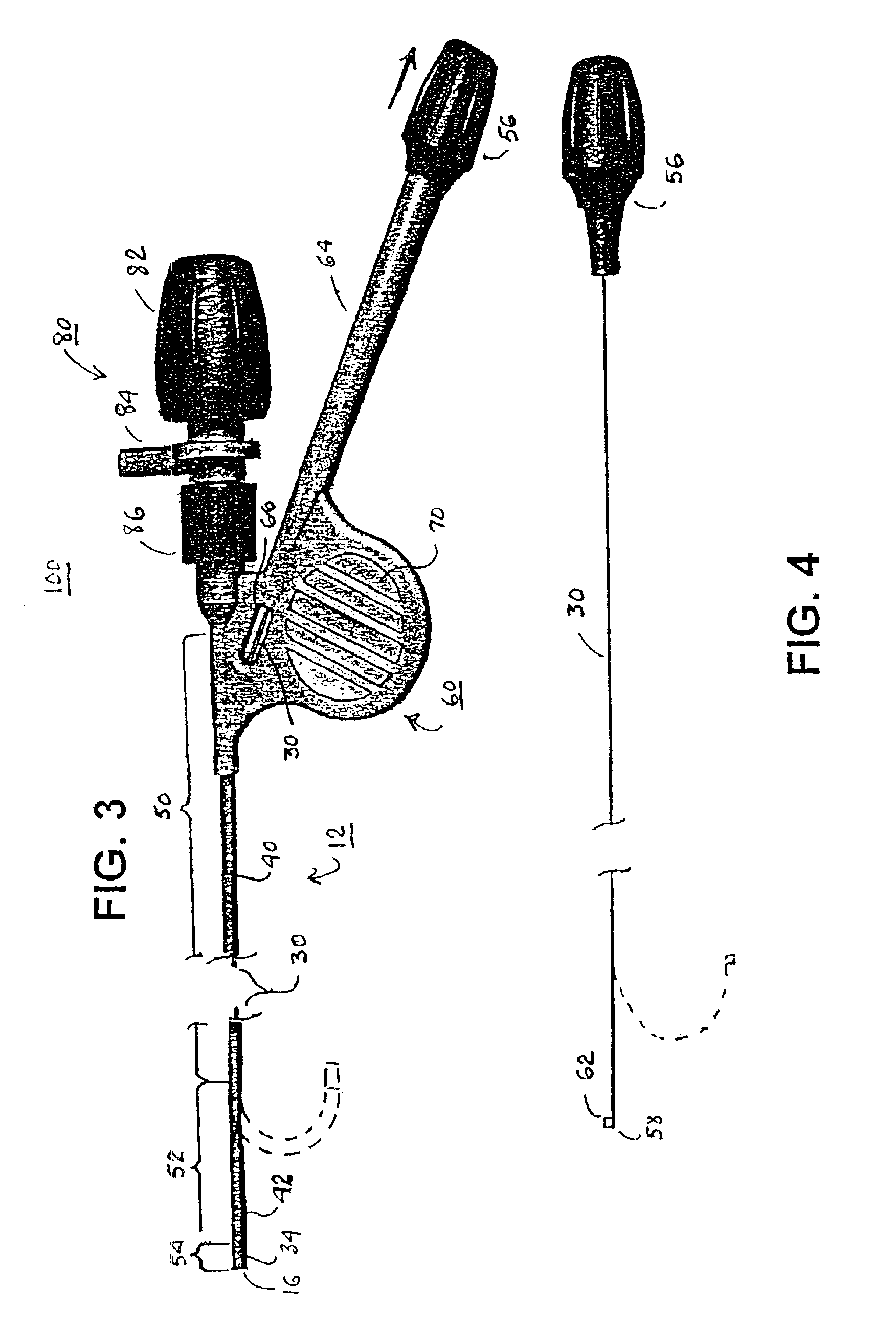
[0046]Thus, the present invention is described in the context of a steerable catheter, and several embodiments are described herein by way of example. First, a multi-lumen catheter body 12 that may incorporate the concepts of this invention is ...


PUM

PropertyMeasurementUnit
Tensile strengthaaaaaaaaaa

Abstract

A steerable catheter and methods of fabrication including a catheter body formed of a continuous wire braid formed of wires braided over a delivery lumen liner and a pull wire lumen liner distal to a pull wire jacket port, braided around the pull wire jacket port to form a braid port, and over at least a portion of the delivery lumen liner proximal to the pull wire jacket port. A pull wire extends from a pull wire proximal end through the pull wire lumen port and through the pull wire lumen to a pull wire distal end. A band is attached to the pull wire distal end and fitted over a distal segment of the wire braid proximal to the catheter body distal end to fix the pull wire distal end to the catheter body and restrain the wire distal end from flaring away from the delivery lumen liner.

Description

FIELD OF THE INVENTION[0001]The present invention relates generally to elongated multi-lumen medical devices adapted to be inserted through an access pathway into a body vessel, organ or cavity to locate a therapeutic or diagnostic distal segment of the elongated medical device into alignment with an anatomic feature of interest, and particularly to a steerable bilumen catheter having a leak resistant delivery lumen.BACKGROUND OF THE INVENTION[0002]Many elongated medical devices are known that are inserted through an access pathway into a body vessel, organ or cavity to locate a therapeutic or diagnostic distal segment of the elongated medical device into alignment with an anatomic feature of interest. For example, catheters, introducers and guide sheaths of various types, drainage tubes, and cannulas are available that extend from outside the body through an access pathway to a site of interest and provide a lumen through which fluids, materials, or other elongated medical devices ...

Claims


Application Information

Patent Timeline
IPC IPC(8): A61M25/00
CPCA61M25/0012A61M25/005A61M25/0147A61M25/0029A61M25/0053A61M25/0054A61M2025/0034A61M2025/0037A61M2025/0177A61M2025/018
Inventor WALDHAUSER, STEVEN L.SKARDA, JAMES R.GESKE, JEFFREY B.SHIPE, GREGORY P.TEISANU, EDUARD T.
Owner MEDTRONIC INC
Learn More