Eureka AIR delivers breakthrough ideas for toughest innovation challenges, trusted by R&D personnel around the world.

Encoder having electrode pattern with pairs of non-conductive portions and multiple sliders that contact the electrode pattern

Inactive Publication Date: 2005-09-20
ALPS ALPINE CO LTD
View PDF11 Cites 5 Cited by
  • Summary
  • Abstract
  • Description
  • Claims
  • Application Information

AI Technical Summary

Benefits of technology

[0016]Accordingly, one embodiment of the present invention provides an encoder which enables detection of high accuracy even if an electrode pattern is relatively roughly formed within a rotation angle used for incrementing or decrementing and which is suitable for miniaturization.

Problems solved by technology

This increases the precision necessary when creating the pattern of the electrode 105, which results in increasing the manufacturing cost and requires an exacting production process such as precision etching or laser processing.

Method used


Image

  • Encoder having electrode pattern with pairs of non-conductive portions and multiple sliders that contact the electrode pattern
  • Encoder having electrode pattern with pairs of non-conductive portions and multiple sliders that contact the electrode pattern
  • Encoder having electrode pattern with pairs of non-conductive portions and multiple sliders that contact the electrode pattern

Examples


Embodiment Construction

[0030]The present invention will be discussed hereinafter in detail in terms of the preferred embodiment according to the present invention with reference to the accompanying drawings. In the following description, numerous specific details are set forth in order to provide a thorough understanding of the present invention. It will be obvious, however, to those skilled in the art that the present invention may be practiced without these specific details. In other instance, well-known structures are not shown in detail in order to avoid unnecessary obscurity of the present invention.

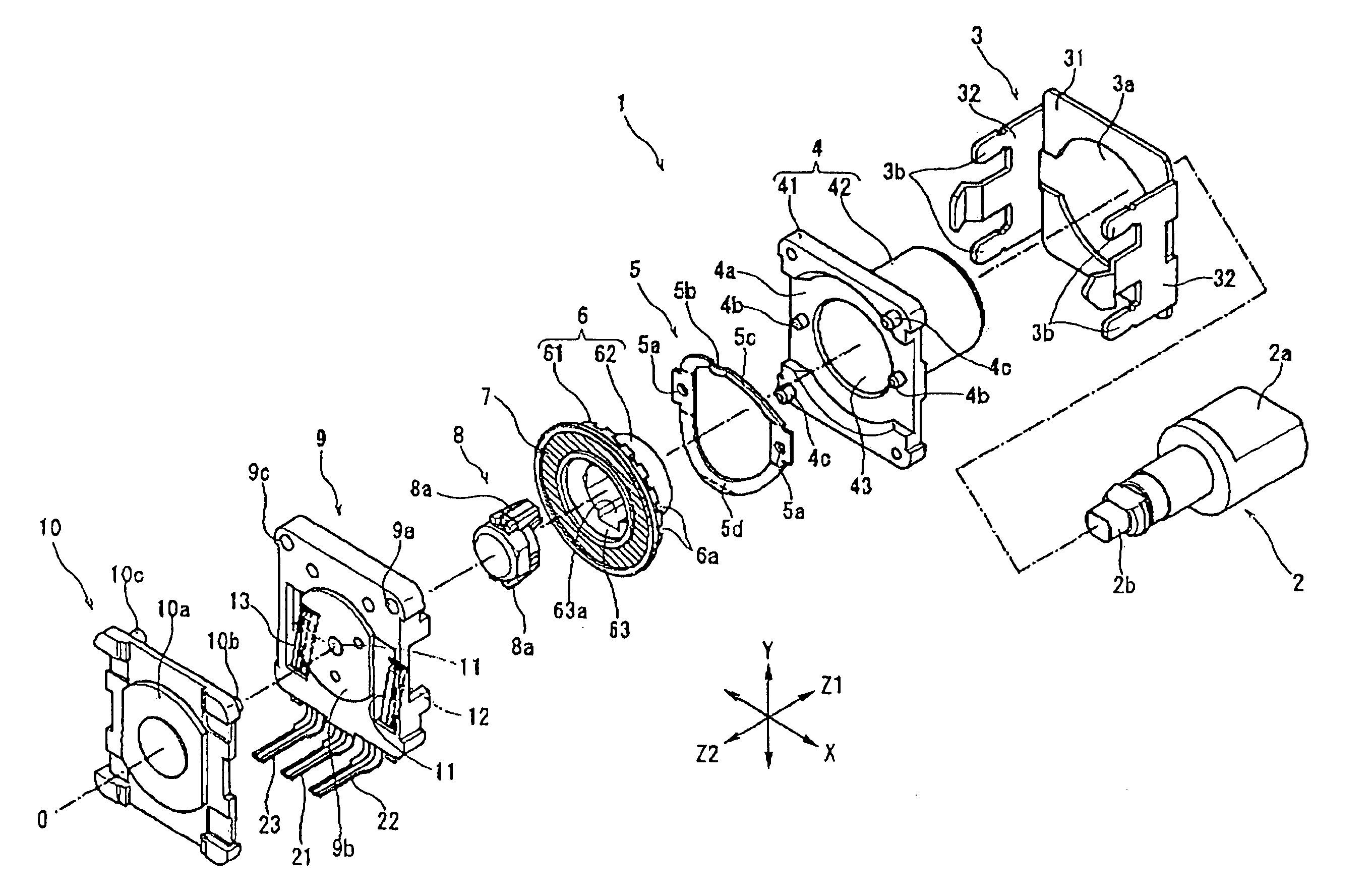
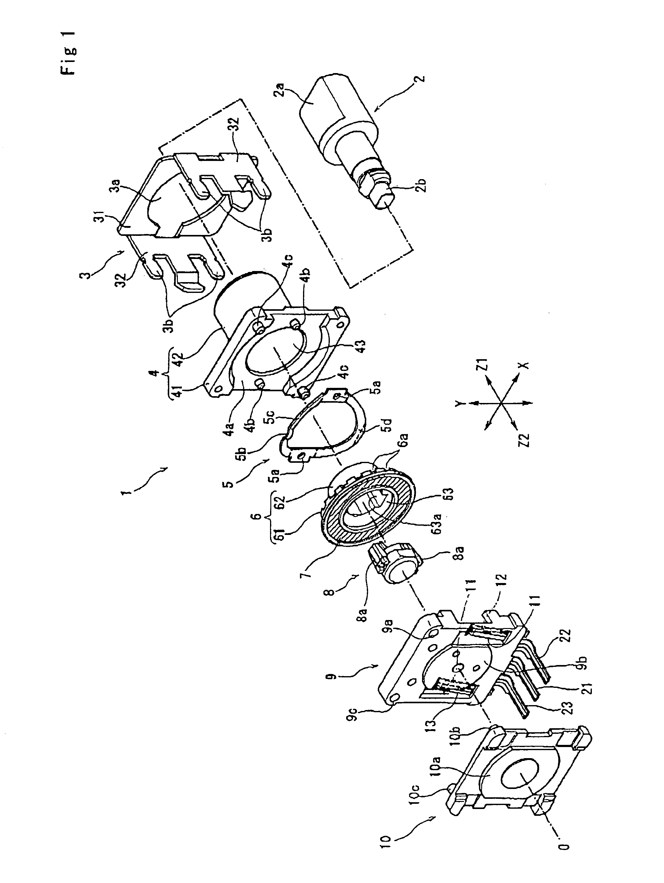
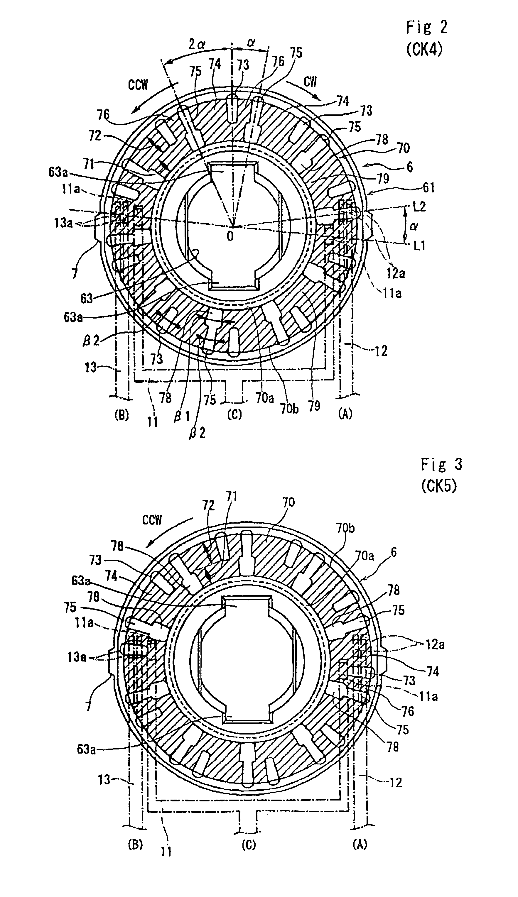
[0031]FIG. 1 is an exploded perspective view of an encoder according to one embodiment of the present invention; FIGS. 2 to 4 are front views showing relative positions between a substrate and sliders for describing operation of the encoder; FIG. 5 is a timing diagram illustrating the operation of the encoder; and FIG. 6 is a block diagram of a detection circuit.

[0032]As shown in FIG. 1, an encoder 1 comp...


PUM


Abstract

An encoder includes a rotary member having a predetermined electrode pattern and a fixed member having multiple channel contacts which are opposed to the electrode. The rotary member has stable reference phases where at most one pair of the contacts is ON (in electrical contact) and at least another pair is OFF (not in electrical contact), i.e. both pairs may be OFF. When the rotary member is rotated clockwise or counter-clockwise from one reference phase, both pairs of contacts are temporarily on before reaching the adjacent reference phase. The pairs of contacts that are ON or OFF at the adjacent reference phase differ dependent on the direction of rotation. A counter is incremented or decremented according to the direction of rotation.

Description

BACKGROUND OF THE INVENTION[0001]1. Field of the Invention[0002]The present invention relates to an encoder in which, as a rotary member is rotated, the states between different combinations of channels switch between a conductive state and a nonconductive state. More particularly, the present invention relates to an encoder in which a pattern of electrode can be easily formed for multiple channels, even if the size of the decoder is decreased.[0003]2. Description of the Related Art[0004]FIG. 7 is an explanatory drawing showing a summary of a construction of a conventional rotary encoder, and FIG. 8 shows wave-form charts (A) and (B) of output from the encoder. For example, an encoder of this kind is disclosed in Japanese Patent No. 2506877.[0005]Conductive sliders 102, 103 and 104 are provided opposite a surface of a disk-shaped substrate 100. On the surface of the substrate 100, a disk-shaped electrode 105, which is formed of a conductive material such as gold, silver and copper, ...

Claims


Application Information

Patent Timeline
IPC IPC(8): H03M1/22G01D5/245G01D5/25H03M1/06H03M1/30
CPCG01D5/2451G01D5/25H03M1/0678H03M1/305
Inventor AIKAWA, KAZUOHAYASHI, HIDEYASU
Owner ALPS ALPINE CO LTD
Why Eureka
Eureka Blog
Learn More