Multipass cavity for illumination and excitation of moving objects

a moving object and multi-pass cavity technology, applied in the field of multi-pass cavity illumination and excitation of moving objects, can solve the problems of reducing the overall intensity of illumination, so as to increase the uniformity of illumination, improve the snr of the instrument, and increase the amount of scattered and/or emitted light

Inactive Publication Date: 2005-09-20
CYTEK BIOSCI
View PDF45 Cites 57 Cited by
  • Summary
  • Abstract
  • Description
  • Claims
  • Application Information

AI Technical Summary

Benefits of technology

[0018]The present invention is directed to an illumination system that is adapted to increase the amount of signal emitted from an object to increase the SNR and to improve the measurement consistency of devices in which the present invention is applied. In general, there is relative movement between the object and the illumination system, and although it is contemplated that either (or both) may be in motion, the object will preferably move while the illumination system is fixed. In addition, it should also be understood that while this discussion and the claims that follow recite “an object,” it is clearly contemplated that the present invention is preferably intended to be used with a plurality of objects and is particularly useful in connection with illuminating a stream of objects.
[0019]The present invention increases the amount of light incident upon an object as the object traverses a field of view, without incurring the expense of additional or more powerful light sources. It also may be configured to increase the uniformity of illumination in the field of view.

Problems solved by technology

There are a number of biological and medical applications that are currently impractical due to limitations in cell and particle analysis technology.
Beyond that point, further reductions in the FOV will fail to improve the SNR because the dominant source of variation in the signal becomes the inherently stochastic nature of the signal.
However, this approach has the undesired effect of reducing the overall intensity of illumination, or photon flux, by spreading the same amount of laser energy over a significantly larger area.

Method used


Image

  • Multipass cavity for illumination and excitation of moving objects
  • Multipass cavity for illumination and excitation of moving objects
  • Multipass cavity for illumination and excitation of moving objects

Examples


Embodiment Construction

[0045]The present invention offers considerable advantages over the prior art for illumination of cells and other types of particles in a flow stream. These advantages arise from the recycling of laser light to increase the photon flux incident upon objects in a flow stream. The present invention can also be configured to improve the uniformity of illumination, while at the same time increasing the photon flux incident upon objects, which is expected to enhance the performance of various flow cytometry applications.

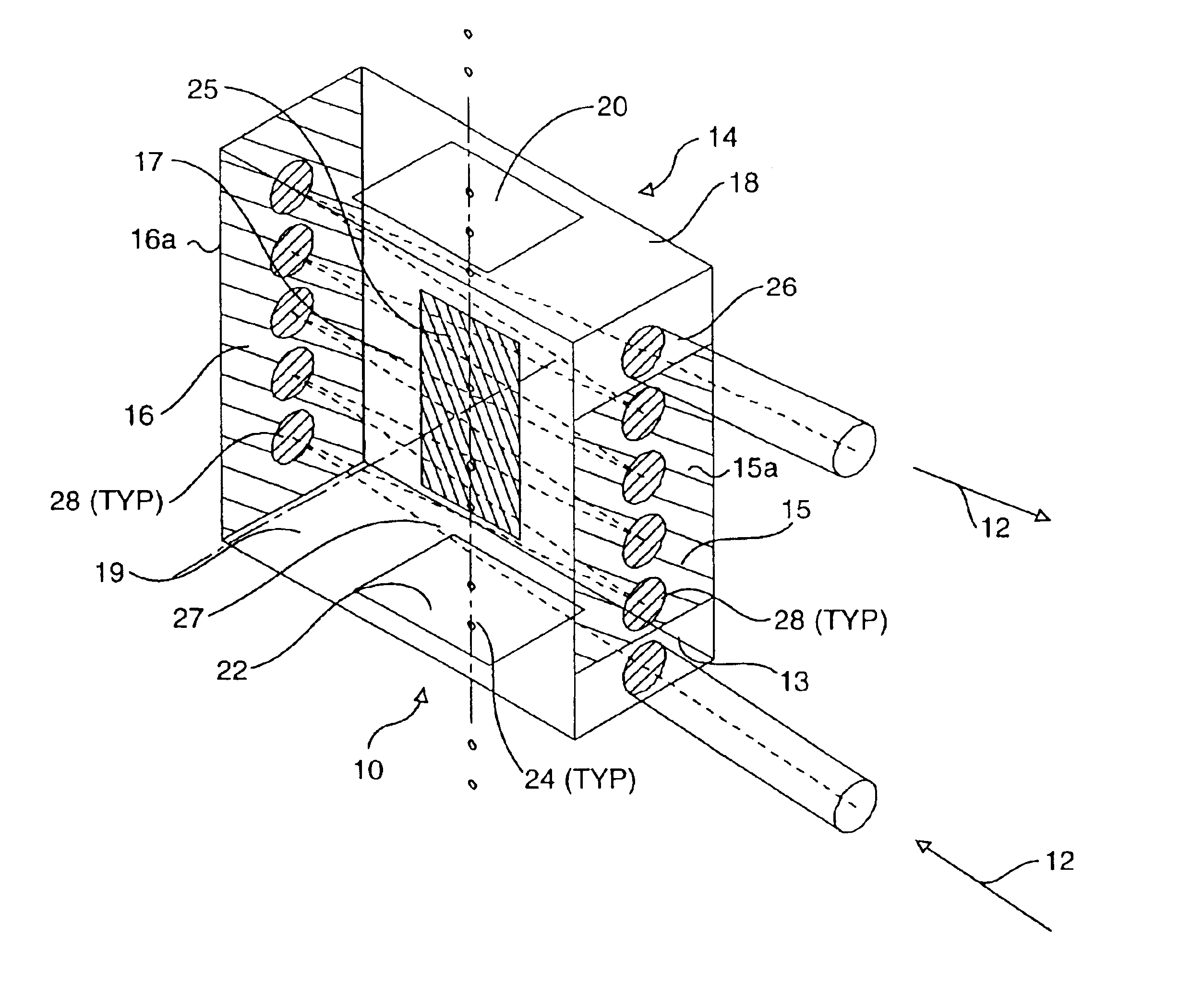
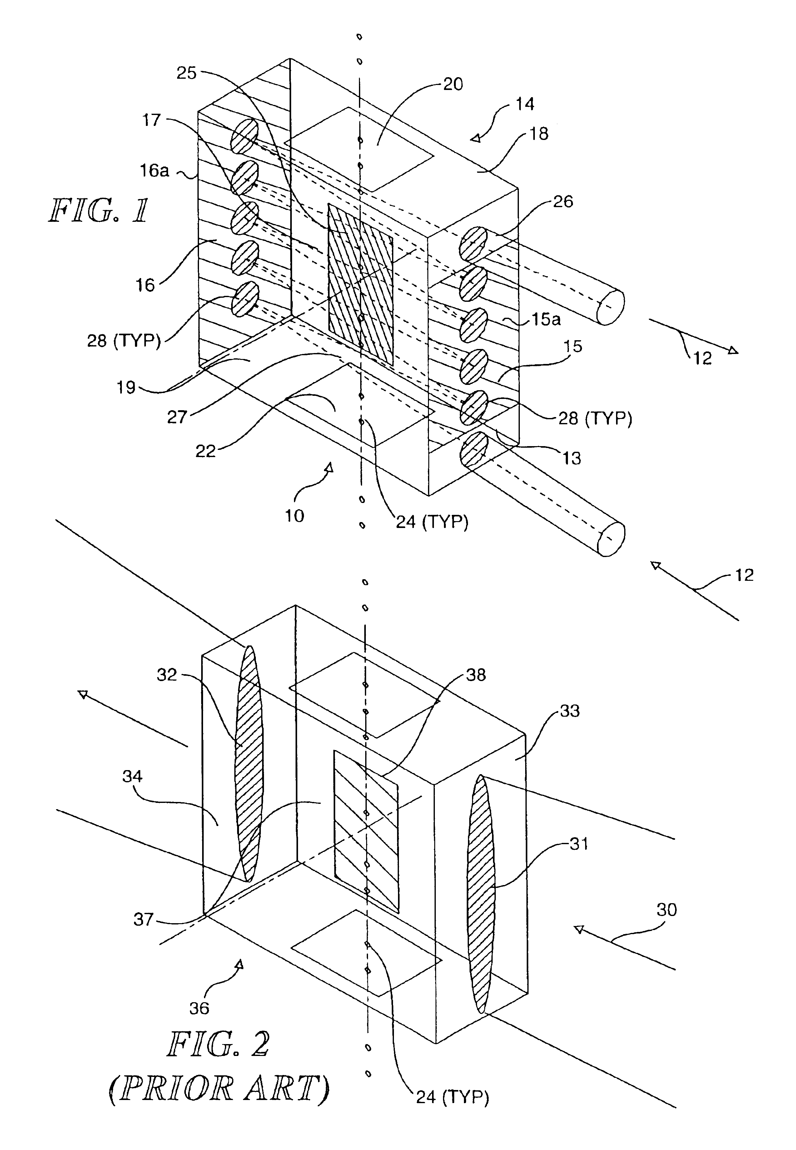
[0046]A first preferred embodiment of an illumination system 10 in accord with the present invention is shown in FIG. 1. Illumination system 10 includes a rectangular solid glass substrate 14 with reflective coatings 15 and 16 applied to two substantially parallel and flat outer surfaces 15a and 16a of the glass substrate. A channel 20 is disposed in the rectangular solid to enable a plurality of objects 24 in a flow stream to pass through illumination system 10 between s...


PUM

PropertyMeasurementUnit
heightaaaaaaaaaa
illuminated heightaaaaaaaaaa
widthaaaaaaaaaa

Abstract

An illumination system for increasing a light signal from an object passing through a reflection cavity. The reflection cavity is defined by spaced-apart, opposed first and second surfaces disposed on opposite sides of a central volume. Preferably the first reflecting surface forms an acute angle with the second reflecting surface. A beam of light is directed into the reflection cavity so that light is reflected back and forth between the first and second surfaces a plurality of times, illuminating a different portion of the central volume with each pass until, having ranged over the central volume, the light exits the reflection cavity. The “recycling” of the light beam in this manner substantially improves the signal to noise ratio of a detection system used in conjunction with the reflection cavity by increasing an average illumination intensity in the central volume.

Description

RELATED APPLICATIONS[0001]This application is a divisional application of U.S. patent application Ser. No. 10 / 355,653, filed on Jan. 29, 2003, (issued as U.S. Pat. No. 6,707,551), which itself is a divisional application of U.S. patent application Ser. No. 09 / 689,172, filed on Oct. 12, 2000 (issued as U.S. Pat. No. 6,580,504), which itself is a continuation-in-part of U.S. patent application Ser. No. 09 / 490,478, filed on Jan. 24, 2000 (issued as U.S. Pat. No. 6,249,341), which itself is a conventional application based on prior Provisional Patent Application Ser. No. 60 / 117,203 filed on Jan. 25, 1999, the benefits of the filing dates of which are hereby claimed under 35 U.S.C. §§ 119(e) and 120.FIELD OF THE INVENTION[0002]This invention generally relates to illumination of moving objects or particles for purposes of analysis and detection, and more specifically, to an apparatus and method for increasing the amount of incident light upon these objects to increase scattered, fluoresce...

Claims


Application Information

Patent Timeline
Patent Type & Authority Patents(United States)
IPC IPC(8): G01N21/64G01N21/03G01N15/14G02B27/00G01N21/85G01J3/28G02B27/14G02B7/28G01N15/10G01N15/02
CPCG01J3/2803G01J3/2823G01N15/147G01N21/031G01N21/6428G01N21/645G01N21/85G02B7/28G02B27/126G01N15/1434G01N2015/0294G01N2015/1006G01N2015/1472G01N2015/1486
Inventor ORTYN, WILLIAM E.BASIJI, DAVID A.FROST, KEITH L.MCRUER, N. ROBERT
Owner CYTEK BIOSCI
Why Eureka
Try Eureka