Method for calibration of a metrology stage

a metrology stage and calibration method technology, applied in the direction of mechanical measuring arrangements, instruments, photomechanical equipment, etc., can solve the problems of systematic measurement error, stage distortion, and typically manifest stage distortion, and achieve the effect of small line width

Inactive Publication Date: 2005-09-27
MICRONIC LASER SYST AB
View PDF13 Cites 22 Cited by
  • Summary
  • Abstract
  • Description
  • Claims
  • Application Information

AI Technical Summary

Benefits of technology

[0017]An advantage with the present invention is that the calibration of a stage may be performed that enhances the possibility to align two or more masks to each other during semiconductor manufacture, especially for very small line widths.

Problems solved by technology

The systematic measurement error is also called stage distortion.
When using these apparatus, stage distortion typically manifests itself as a coordinate measurement error when measuring marks having known positions on a rigid artefact plate (“standard plate”).
Unfortunately, the use of standard plates to calibrate 2D metrology stages is no longer generally feasible because it is difficult to fabricate plates with mark positions at locations known with higher levels of accuracy than the levels obtainable with state-of-the-art metrology tools.
However, the algorithm proposed was computationally expensive because it was non-linear and possible unstable in the presence of large random measurement noise.
A disadvantage with the method is that a rigid artefact plate having a two-dimensional N×N array of marks thereon, having a predetermined interval, has to be provided when making the measurements.
Another disadvantage is that the rotation has to be ±90° and the translation has to be at least one interval.

Method used


Image

  • Method for calibration of a metrology stage
  • Method for calibration of a metrology stage
  • Method for calibration of a metrology stage

Examples


Embodiment Construction

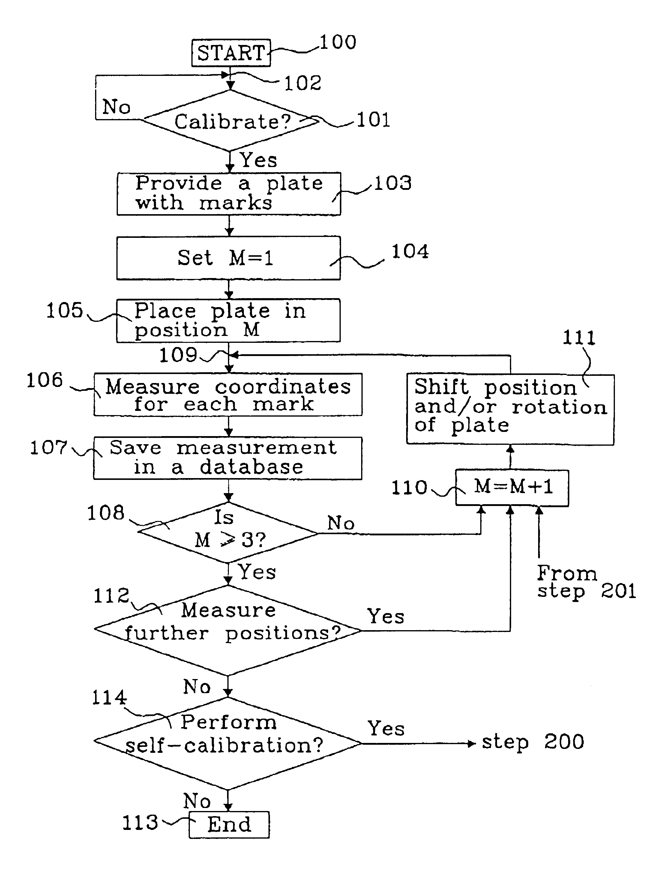
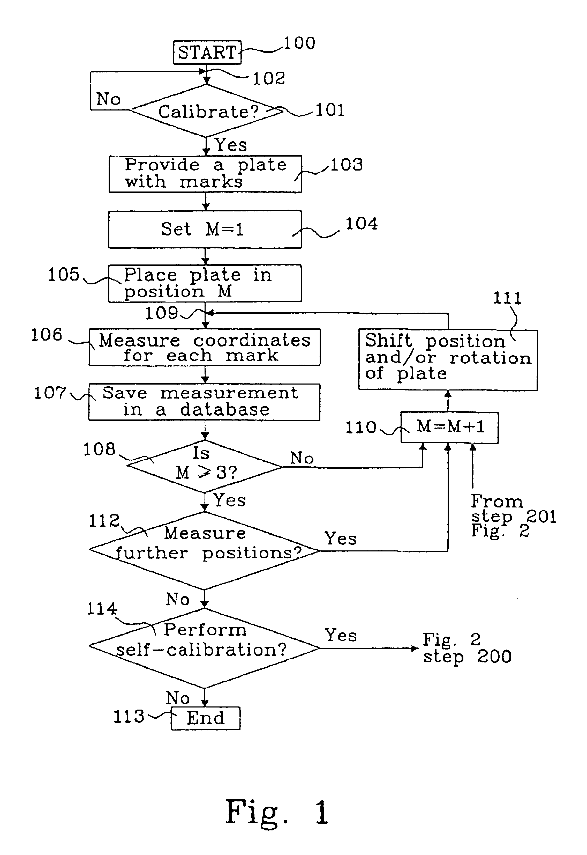
[0022]The principal that the method according to the invention is based upon makes it possible to use a calibration plate which is provided with a number of marks arbitrarily scattered across the surface of the plate. A plate provided with N ×N arrays of marks in a grid structure may naturally also be used. The method will provide a possibility to determine the stage distortion function S (x,y) and also the plate distortion function P (x,y) provided at least three different measurement views has been measured including transitional movement and rotational movement as illustrated in connection with examples below.

[0023]The errors between measured positions (ui,vi) and the Cartesian coordinates (xi,yi) for each measurement point i is a result of errors in the plate and / or errors in the stage. Normally both the plate and the stage contribute to the error in measurement.

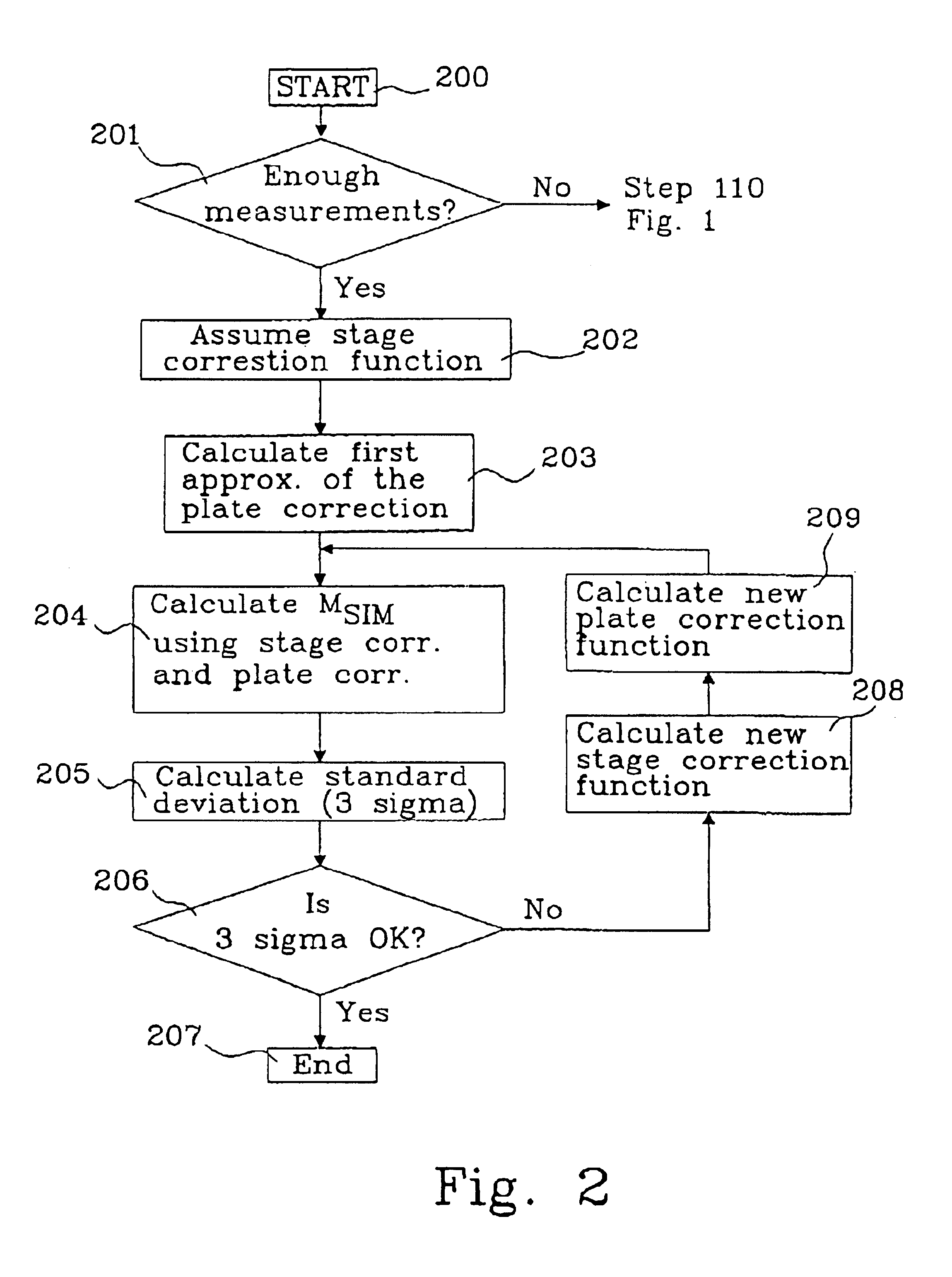
[0024]The self-calibration is generally performed in the following steps:

[0025]1. A calibration plate with marks arbit...


PUM


Abstract

The present invention relates to a method for calibrating a metrology stage in at least two dimensions using an artefact plate having marks forming a pattern, comprising the steps of: placing the artefact plate on the metrology stage in at least three positions, assuming the geometrical properties of the metrology stage and the artefact plate, and the positions of the artefact plate for each measurement, forming a model predicting the measurements of the artefact plate, measuring the marks by the metrology stage, and inverting said model to improve the assumptions on metrology stage and artefact plate.

Description

TECHNICAL FIELD[0001]The present invention relates to a method for calibration of a metrology stage in a measuring apparatus, preferably a pattern generating apparatus, as defined in claim 1 and claim 5.BACKGROUND TO THE INVENTION[0002]Two-dimensional (2D) coordinate stages are used in many stages of very-large-scale-integrated (VLSI) circuit fabrication, to position lithography masks and move wafers to predetermined positions with high degree of reproducibility and accuracy. Typical tools which incorporate 2D-coordinate stages include electron and laser beam pattern generators in mask making, optical steppers in wafer printing and placement inspection tools in mask metrology.[0003]In conventional photolithographic processing of semiconductor wafers, a plurality of masks is used in sequence to define microelectronic structures and features therein. Of course, in order to ensure that the features produced with a first mask are properly aligned to features produced with a second mask ...

Claims


Application Information

Patent Timeline
Patent Type & Authority Patents(United States)
IPC IPC(8): G01B21/02G01B21/04G01B1/00G01D21/00G03F7/20
CPCG01B21/045G03F7/70516G03F7/70716G01D21/00
Inventor STIBLERT, LARSEKBERG, PETER
Owner MICRONIC LASER SYST AB
Why Eureka
Try Eureka