Expansion turbine stage

a technology of expansion turbine and expansion turbine, which is applied in the direction of motors, jet propulsion plants, air transport, etc., can solve the problems of reducing the effectiveness and affecting the efficiency of the expansion turbine stage, so as to achieve the effect of reducing heat transport between the entering and exiting gas stream, reducing heat conductivity, and increasing efficiency

Inactive Publication Date: 2005-09-27
ATLAS COPCO ENERGAS
View PDF22 Cites 2 Cited by
  • Summary
  • Abstract
  • Description
  • Claims
  • Application Information

AI Technical Summary

Benefits of technology

[0006]It is therefore an object of the present invention to increase the degree of effectiveness of -the turbine stage in an expansion turbine having the characteristics described initially.
[0007]This object is achieved, according to the invention, by arranging the out-flow diffuser in a holder bore in the housing, as a separate component. The out-flow diffuser is made from a non-metallic material having a low heat conductivity, for thermal insulation of the housing relative to the cold expanded gas stream. In this way, the heat transport between the entering and the exiting gas stream is significantly reduced. On the one hand, heating of the expanded gas is clearly weakened, so that this gas has a very low enthalpy. On the other hand, cooling of the compressed gas stream that is fed in is also clearly reduced, so that the compressed gas stream has a very high enthalpy when entering into the turbine rotor. The two gas streams therefore have a very great difference in enthalpy, which allows a correspondingly great technical work to be obtained, according to the teaching of thermodynamics. The irreversibilities caused by heat conduction in the expansion turbine stage are significantly reduced using the measure according to the invention, so that an approximation of the isentropic ideal case results. In the final analysis, the invention allows a significant increase in the degree of effectiveness of the turbine.
[0008]Preferably, the out-flow diffuser is made of a plastic having a heat conductivity of less than 2 W / (mK). According to a particularly preferred embodiment of the invention, the plastic is made of a polyolefin suitable for low-temperature applications, particularly a polyethylene or polyethylene copolymer having an ultra-high molecular weight (PE-UHMW). This plastic demonstrates sufficient impact strength and wear resistance even at cryogenic gas turbine temperatures as low as −200° C. This capability is particularly advantageous when using the turbine stage in air separation plants.

Problems solved by technology

Known expansion turbine stages having the characteristics described initially have drawbacks encountered in practice.
At great temperature differences between the entering compressed gas and the expanded gas exiting from the turbine rotor, the effectiveness of these stages is reduced because of the heat exchange between these two gas streams, as the result of heat conduction in the turbine.
In this connection, the heat transport into the out-flow diffuser from the housing is a particular problem.
This reduction in turn reduces the technical work gained at the turbine rotor and thereby reduces the degree of effectiveness of the turbine.
This problem is significant, in particular, in the case of very low, particularly cryogenic temperature ranges, in which turbine stages of the type being described are frequently used.

Method used


Image

  • Expansion turbine stage
  • Expansion turbine stage

Examples


Embodiment Construction

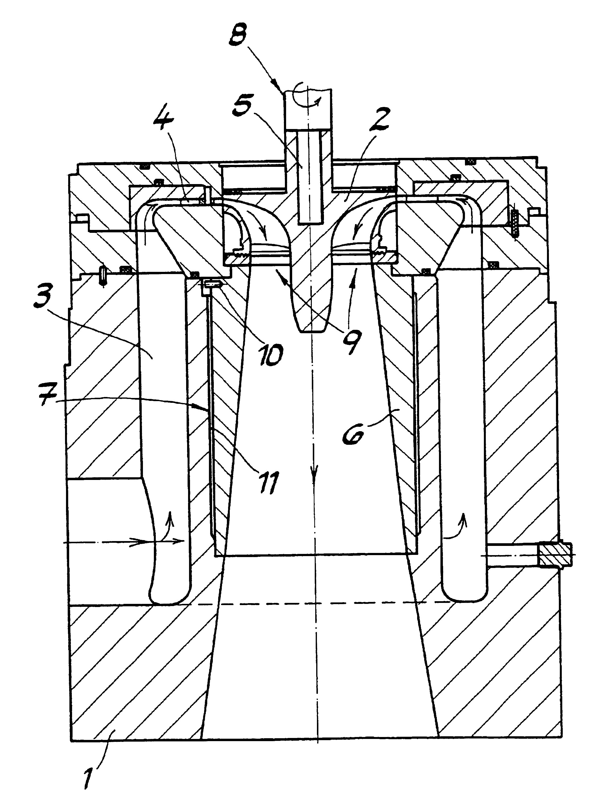
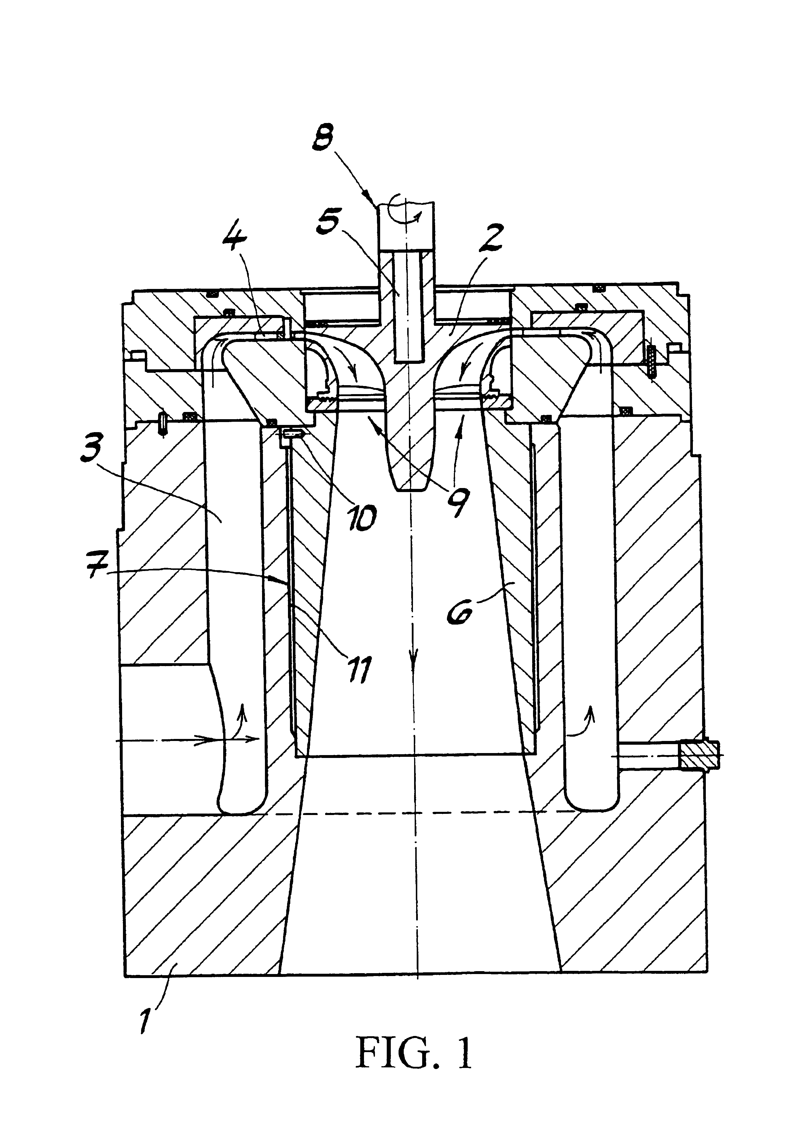
[0012]FIG. 1 shows an expansion turbine stage for compressed gases, having a housing 1 and a turbine rotor 2. Housing 1 has flow guide channels 3 and jets 4 connected to them downstream, for feed of the compressed gas to turbine rotor 2. Turbine rotor 2, arranged on a shaft end 5 in over-mounted manner, and having centripetal flow through it, is followed by an out-flow diffuser 6 enclosed by housing 1 to delay the cold expanded gas. Diffuser 6 extends coaxially to turbine rotor 2, as an extension of shaft end 5. Out-flow diffuser 6 is arranged in a holder bore 7 in housing 1, as a separate component. For thermal insulation of housing 1 relative to the cold expanded gas stream, out-flow diffuser 6 is made of a non-metallic material having a low heat conductivity. The heat transport between the entering gas stream and the exiting gas stream due to heat conduction in housing 1 and in out-flow diffuser 6 is clearly reduced thereby. On the one hand, heating of the expanded gas stream can...


PUM


Abstract

An expansion turbine stage for compressed gases has a housing and a turbine rotor. The housing has flow guide channels for feeding the compressed gas to the turbine rotor. The turbine rotor, which is over-mounted and has centripetal flow through it, is followed by an out-flow diffuser enclosed by the housing, to delay the cold expanded gas. The out-flow diffuser is arranged in a holder bore in the housing, as a separate component. For thermal insulation of the housing relative to the cold expanded gas stream, the out-flow diffuser is made of a non-metallic material having a low heat conductivity.

Description

CROSS REFERENCE TO RELATED APPLICATIONS[0001]Applicant claims priority under 35 U.S.C. §119 of German Application No. 103 10 678.2 filed Mar. 12, 2003.BACKGROUND OF THE INVENTION[0002]1. Field of the Invention[0003]The present invention relates to an expansion turbine stage for compressed gases, having a housing and a turbine rotor. The housing has flow guide channels for feeding the compressed gas to the turbine rotor. The turbine rotor is over-mounted and has centripetal flow through it. An out-flow diffuser enclosed by the housing follows the overhung turbine rotor to delay the cold expanded gas.[0004]2. The Prior Art[0005]Known expansion turbine stages having the characteristics described initially have drawbacks encountered in practice. At great temperature differences between the entering compressed gas and the expanded gas exiting from the turbine rotor, the effectiveness of these stages is reduced because of the heat exchange between these two gas streams, as the result of h...

Claims


Application Information

Patent Timeline
Patent Type & Authority Patents(United States)
IPC IPC(8): F01D25/14F01D1/00F01D25/08F01D1/08F02C1/02F02C1/00
CPCF01D1/08F01D25/145F02C1/02Y02T50/675Y02T50/60
Inventor BOSEN, WERNER
Owner ATLAS COPCO ENERGAS
Why Eureka
Try Eureka