
Ultrasonic annular core bit

a technology of annular core and ultrasonic core, which is applied in the direction of cutting machines, stone-like material working apparatuses, sawing apparatuses, etc., can solve the problem of no robust axial longitudinal oscillations, and achieve the effect of avoiding the occurrence of axial longitudinal oscillations

Inactive Publication Date: 2005-09-27
HILTI AG
View PDF6 Cites 53 Cited by
  • Summary
  • Abstract
  • Description
  • Claims
  • Application Information

AI Technical Summary

Benefits of technology

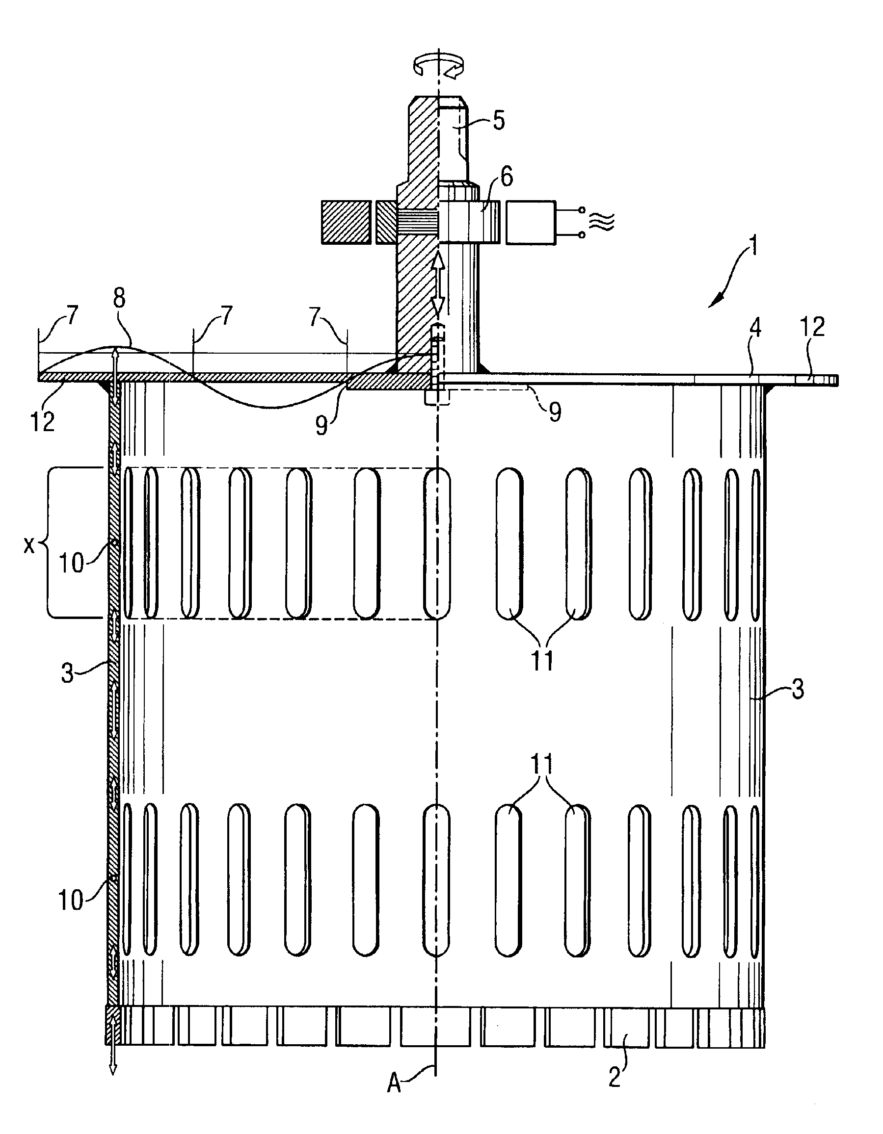
[0012]The combination of separate parts, the cover and the cylindrical tube, dimensioned in accordance with a set excitation frequency, insures a robust excitation behavior of the annular core bit with an axial ultrasonic excitation.
[0014]The provision of the concentric projection in the vicinity of the location of the nodal circle of amplitude oscillations leads to an amplitude transformation with a significant increase of the amplitude of nodal points at a location where the projection extends into the cylindrical tube. As a result, axial longitudinal oscillations with a significantly increased amplitude are excited in the cylindrical tube, so that the cylindrical tube is adequately excited. The nodal circle of the amplitude oscillation is located in the vicinity of the location of the amplitude oscillation nodes of the concentric radial waves which results, with a radial projection, in a small displacement of the position of the amplitude oscillation nodes.
[0018]Advantageously, the elongate recesses extend parallel to the tube axis, which prevents excitation of parasitic shear modes.
[0020]Advantageously, the cover has a concentric projection in a vicinity of a location of a nodal circle of amplitude oscillations of the concentric flexural oscillation, which further increases the amplitude.
[0022]In addition to a cover that directly covers the cylindrical tube, advantageously, there is provided a cover with a collar projecting radially beyond the cylindrical tube, advantageously, by a one-fourth of the wave length of the flexural oscillation. This additionally eliminates radial modes excited in the cylindrical tube.

Problems solved by technology

This is because upon engaging the to-be-cut component, with a larger diameter of the tube, i.e., with a large ratio of the tube diameter to the excitation diameter of the actor, no robust axial longitudinal oscillations are excited, in particular, with high damping imparted to the cylindrical tube by axial forces necessary for effecting an abrasive cutting.

Method used


Image

  • Ultrasonic annular core bit
  • Ultrasonic annular core bit

Examples


Embodiment Construction

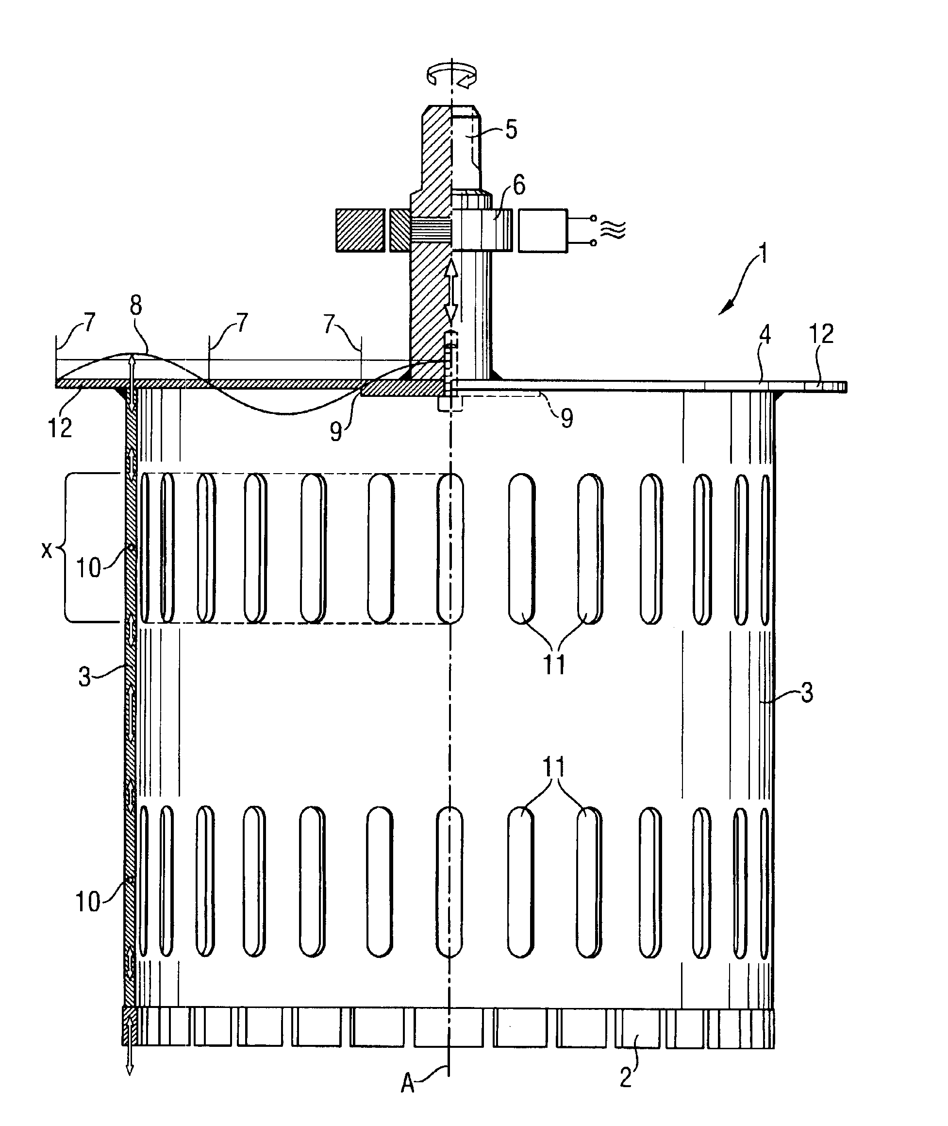
[0026]A large diameter ultrasonic annular core bit 1 according to the present invention, which is shown in the drawing, has a thin-wall cylindrical tube 3 provided with a plurality of abrasive bodies 2 at one end of its end side, and a thin-wall cover 4 secured to another, opposite end side of the cylindrical tube 3. The cover 4 is provided with a shank 5 to e received formlockingly in a chuck of a power tool (not shown). The shank 5 is arranged symmetrically with respect to the cylindrical tube 3 and the cover 4 and has its axis coinciding with the axis A of the core bit 1. Within the shank 5, there is arranged a schematically shown portion of electroacoustic actor 6 in form of a piezoconverter fed with inductive voltage from a phase transformer. The portion of the actor 6 in the shank 5 serves for inciting an axial ultrasonic oscillation. The cover 4 has, at a radial point of a nodal circle 7 of amplitude oscillations, a flexural self-oscillation 8 having an amplitude maximum on t...


PUM

PropertyMeasurementUnit
natural frequencyaaaaaaaaaa
diameteraaaaaaaaaa
oscillation frequencyaaaaaaaaaa

Abstract

A core bit for abrasive cutting including a cylindrical tube (3) provided at its end surface with cutting or abrasive bodies (2) and a cover (4) provided at an opposite end surface of the cylindrical tube (3) and secured thereto and having, along its central axis (A), a shank (5) to be received in a rotary power tool, with the cover (4) being dimensioned, with respect to a set excitation frequency, for forming a whole number of maximum amplitude oscillations of a concentric flexural oscillation, and the cylindrical tube (3) being dimensioned, with respect to a set excitation frequency, for forming a whole number of maximum amplitude oscillations of axial longitudinal oscillations.

Description

BACKGROUND OF THE INVENTION[0001]1. Field of the Invention[0002]The present invention relates to a rotatable about an axis of symmetry, ultrasonic annular core bit provided with cutting or abrasive bodies for abrasive cutting mineral components formed, e.g., of stone and having axial ultrasonic excitation.[0003]2. Description of the Prior Art[0004]Usually, a pot-shaped, annular core bit includes a cylindrical tube provided with abrasive bodies at its end side, and a cover provided at the opposite end side of the cylindrical tube and secured thereto and having, in its center, a shank to be received in a rotary power tool. Upon a conventional superimposition of ultrasound in the range from 20 kHz to 200 kHz at the natural frequency of the core bit, the bit will be excited in its center by an actor in the shank provided in the cover. Such core bits can be only realized with cylindrical tubes having only a small diameter up to 100 mm. This is because upon engaging the to-be-cut componen...

Claims


Application Information

Patent Timeline
Patent Type & Authority Patents(United States)
IPC IPC(8): B24B1/04B24B33/08B24B33/00B28D1/04B28D1/02B23B51/04B28D1/00B28D1/14
CPCB24B1/04B24B33/08B28D1/041Y10T408/895Y10T408/8957Y10T408/896
Inventor CRAMER, TILLKAUF, ADRIANTICHY, STEFANLITTMANN, WALTERVAN TAACK-TRAKRANEN, JOHNALBERG, PETER
Owner HILTI AG
Learn More