This helps you quickly interpret patents by identifying the three key elements:
Problems solved by technology
Method used
Benefits of technology
[0020]The present design reduces the energy waste that usually occurs in driving the actuator's armature. An armature sensor monitors the armature movement or determines when the armature has reached the end of its travel. At a selected point, based on a signal from the armature sensor, a drive signal to the actuator-coil drive ends. This can reduce energy consumption greatly, because coil-drive duration thereby does not always need to be long enough to meet worst-case requirements usually applied when there is no armature sensor. This can result in a significant battery-longevity increase.
[0021]According to another aspect, the valve actuator can use materials with a high magnetic permeability such as the ferromagnetic types of stainless steel regardless of their low corrosion-resistivity and the armature does not need to be subjected to a number of treatmen
Problems solved by technology
In non-latching actuators, unnecessarily high drive current for holding the valve open also may unnecessarily reduce the battery's longevity.
This usually causes degradation of the armature (i.e., corrosion) and problems with metal and other ions (or other deposits) that accumulate within the bobbins cavity.
However, materials with very high magnetic permeability have usually low corrosio
Method used
Image
Click on the blue label to locate the original text in one second.
Reading with bidirectional positioning of images and text.
Examples
Example
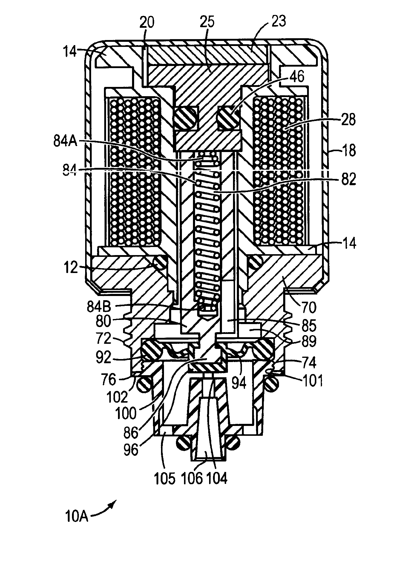
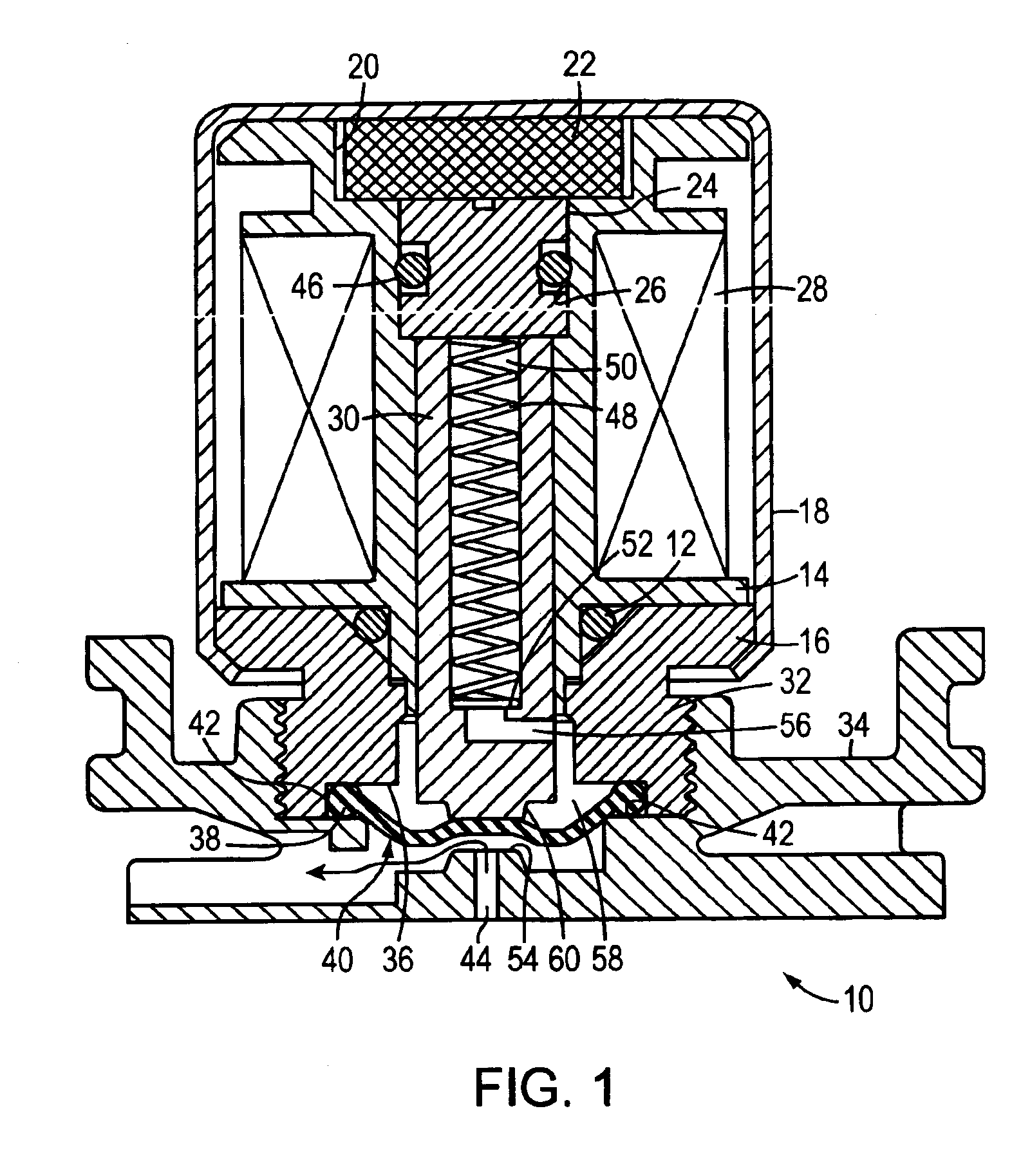
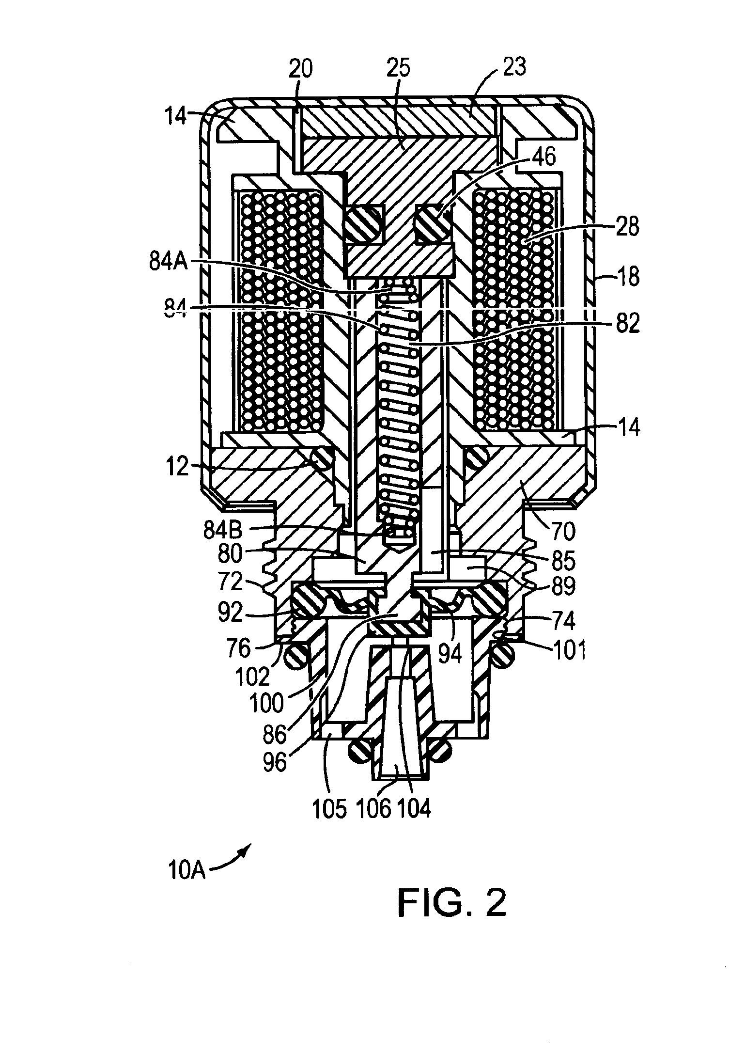
[0028]Referring to FIG. 1, industrial, agricultural and household systems use various types of valves for controlling fluid flow. An electrically operable valve 10 uses a solenoid to drive a plunger into a valve seat and thereby stop flow through a conduit in which the valve seat is disposed. Specifically, valve actuator 10 includes an actuator base 16, a ferromagnetic pole piece 24, a ferromagnetic armature 30, slideably mounted in an armature pocket formed in pole piece 24, and a solenoid windings 28 wound about a solenoid bobbin 14. Valve 10 also includes a resiliently deformable O-ring 12 that forms a seal between solenoid bobbin 14 and actuator base 16, all of which are held together by a housing 18. At its upper end, bobbin 14 forms a magnet recess 20 formed for a disk-shaped magnet 22. Solenoid housing 18 (i.e., can 18) is crimped at actuator base 16 to hold magnet 22 and pole piece 24 against bobbin 14 and thereby secure windings 28 and actuator base 16 within can 18.
[0029]V...
PUM
Abstract
An actuator base, bobbin, and pole piece form a pocket for an armature that a flexible membrane encloses to form an armature chamber filled with an incompressible fluid. The membrane protects the armature from exposure to corrosive fluids flowing in a conduit. Conduit flow can be stopped by driving the membrane against a valve seat. Pressure from the controlled fluid in the conduit is transmitted through the membrane to the fluid within the armature chamber so that the armature does not need to counteract force applied to the membrane by the conduit fluid's pressure.
Description
[0001]This application is a continuation of PCT Application PCT / US01 / 51098 filed on Oct. 25, 2001, which is a continuation-in part of U.S. application Ser. No. 09 / 696,154 filed on Oct. 25, 2000 now U.S. Pat. No. 6,609,698, entitled “Ferromagnetic / Fluid Valve Actuator.” The PCT Application PCT / US01 / 51098 is also a continuation-in part of U.S. application Ser. No. 09 / 924,130, filed on Aug. 7, 2001 now U.S. Pat. No. 6,450,478, entitled “Reduced-Energy Consumption Actuator.” The PCT Application PCT / US01 / 51098 is also a continuation-in part of U.S. application Ser. No. 10 / 037,473, filed on Oct. 19, 2001 now abandoned, which in turn is a continuation of U.S. application Ser. No. 09 / 514,491, filed on Feb. 29, 2000, now U.S. Pat. No. 6,305,662, entitled “Reduced-Energy Consumption Actuator.” The above-cited applications are incorporated by reference for all purposes.BACKGROUND OF THE INVENTION[0002]1. Field of the Invention[0003]The present invention relates to controlling fluid flow in var...
Claims
Application Information
Patent Timeline
Application Date:The date an application was filed.
Publication Date:The date a patent or application was officially published.
First Publication Date:The earliest publication date of a patent with the same application number.
Issue Date:Publication date of the patent grant document.
PCT Entry Date:The Entry date of PCT National Phase.
Estimated Expiry Date:The statutory expiry date of a patent right according to the Patent Law, and it is the longest term of protection that the patent right can achieve without the termination of the patent right due to other reasons(Term extension factor has been taken into account ).
Invalid Date:Actual expiry date is based on effective date or publication date of legal transaction data of invalid patent.