Injection molding process and injection molding apparatus for thermoplastic resin molded articles

a technology of injection molding process and thermoplastic resin, which is applied in the direction of mixing/kneading with horizontally mounted tools, manufacturing tools, food shaping, etc., can solve the problems of difficult injection of gas into molten resin, difficulty in industrial application, and several tens of hours, so as to achieve little or no harm

Inactive Publication Date: 2005-09-27
SEKISUI CHEM CO LTD
View PDF15 Cites 38 Cited by
  • Summary
  • Abstract
  • Description
  • Claims
  • Application Information

AI Technical Summary

Benefits of technology

[0029]The blowing agent for use in the present invention is not limited specifically insofar as the agent is nonreactive with the resin, will not deteriorate the resin or produces no adverse effect on the resin. Examples of useful agents are inorganic gases such as carbon dioxide, nitrogen, argon, neon helium and oxygen, and organic gases such as chlorofluorocarbons and low molecular weight hydrocarbons.
[0030]Preferable among these

Problems solved by technology

However, although capable of affording a thermoplastic resin expanded body, the former method of incorporating the nonreactive gas into the solid material resin requires several tens of hours to saturate the resin with the gas for incorporation, for example, because there is a need to incorporate the gas into the resin within a pressure-resistant chamber, with the supply of resin to the molding machine interrupted, in order to complet

Method used


Image

  • Injection molding process and injection molding apparatus for thermoplastic resin molded articles
  • Injection molding process and injection molding apparatus for thermoplastic resin molded articles
  • Injection molding process and injection molding apparatus for thermoplastic resin molded articles

Examples


Embodiment Construction

[0037]A mode of carrying out the invention will be described below in detail with reference to the drawings.

[0038]The drawings show an embodiment of injection molding apparatus of the invention.

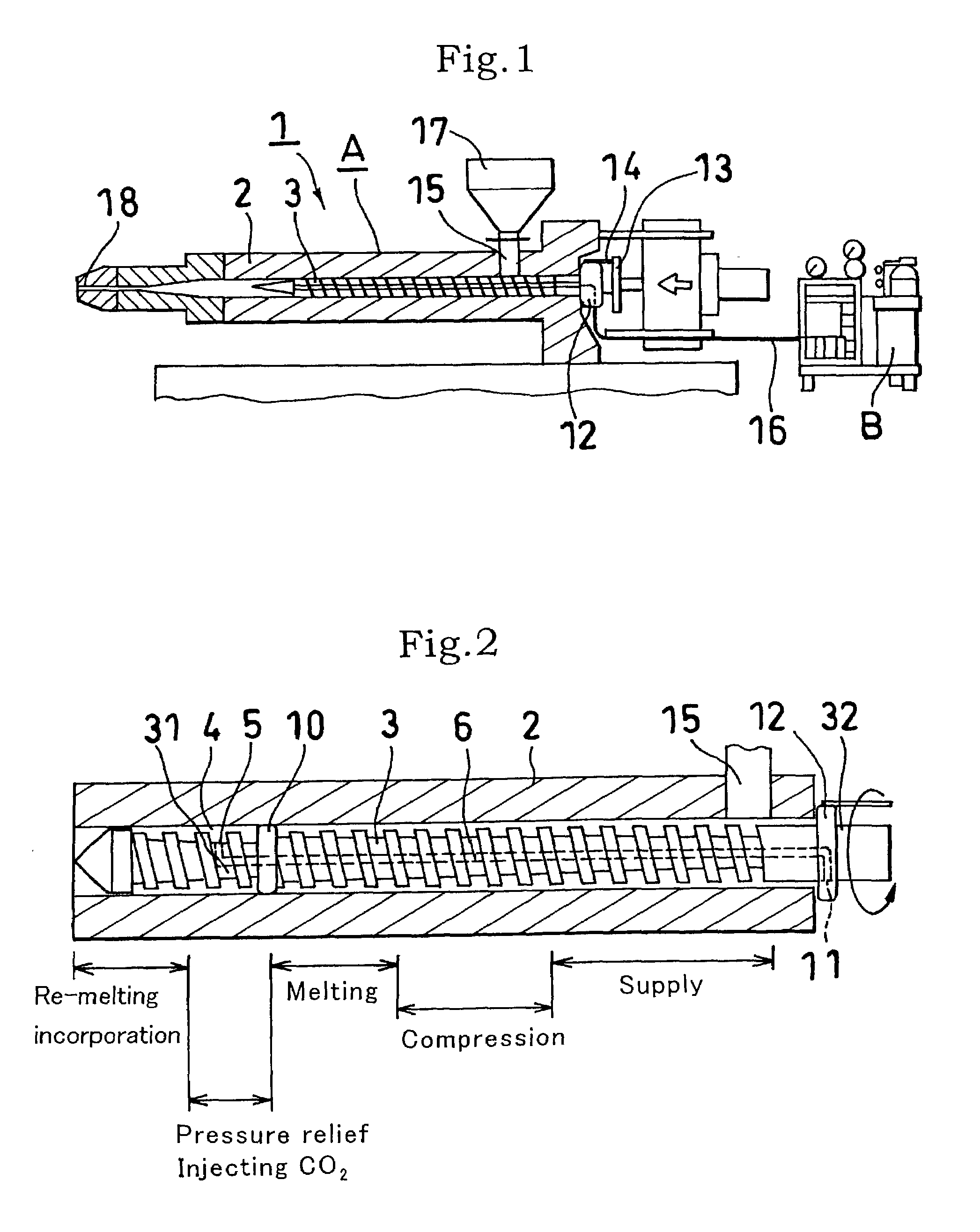
[0039]As shown in FIG. 1, the injection molding apparatus A comprises an injection molding machine 1 and a gas injector B for feeding a gas to the machine. The injection molding machine 1 consists mainly of a cylinder 2 and a screw 3 disposed inside the cylinder.

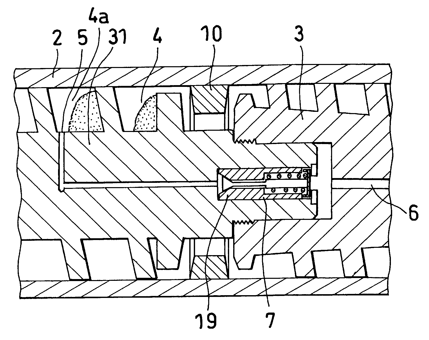
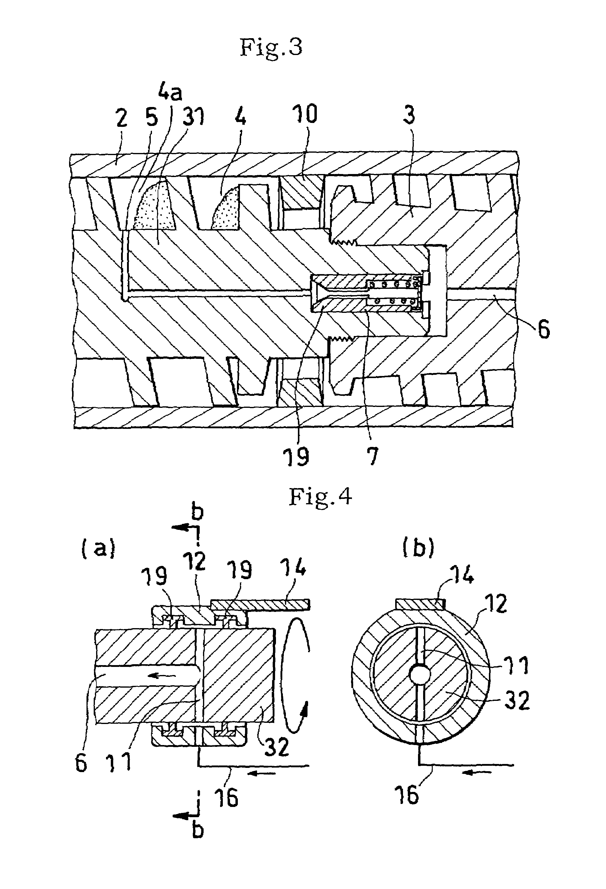
[0040]As shown in FIGS. 2 and 3, the screw 3 has an enlarged incorporating zone forming portion 31 of the following construction in the vicinity of the front end (the downstream end) of the screw (at a position slightly rearward, namely toward a hopper, from the front end). This portion 31 has a deeper screw groove than the other portion of the screw 3. As a result, the portion 31 has a greater distance between the inner surface of the cylinder 2 and the outer surface of the screw shaft, and the front and rear screw flights of this po...


PUM

PropertyMeasurementUnit
Pressureaaaaaaaaaa
Stabilityaaaaaaaaaa

Abstract

An object of the invention is to provide an injection molding process for preparing thermoplastic resin molded articles and an injection molding apparatus for use in practicing this process, the process and the apparatus being adapted to supply a blowing agent, especially a nonreactive gas such as carbon dioxide or nitrogen gas, to a thermoplastic resin continuously at a relatively low pressure with good stability to incorporate the agent or gas into the resin. As shown in FIG. 3, a resin in a cylinder (2) of an injection molding machine (1) as melted by rotating a screw (3) is mixed and dissolves carbon dioxide which is supplied to the molten resin from a gas supply opening (5) formed in the screw (3). An amount of the gas-incorporating molten resin is measured out and injected into a mold cavity to obtain an expansion-molded article. To incorporate carbon dioxide into the molten resin, the gas is supplied from a gas inlet (11) formed in a rear end portion of the screw to a portion (4a) not fed with the resin and positioned between front and rear screw flights and closer to the front flight, through a gas supply channel 6 extending through the screw and via the supply opening (5).

Description

TECHNICAL FIELD[0001]The present invention relates to a process for producing thermoplastic resin molded articles, especially thermoplastic resin expansion-molded articles or molded articles of a thermoplastic resin which has a high melt viscosity and is not amenable to melt molding, and an injection molding apparatus useful for this process.BACKGROUND ART[0002]Processes for preparing thermoplastic resin expanded bodies by injection molding includes a process wherein carbon dioxide, nitrogen gas or like nonreactive gas serving as a blowing agent is incorporated into the molten resin and then the resin is injected into a mold for expansion.[0003]Such expanding nonreactive gas is incorporated into the molten resin by 1) a method wherein the nonreactive gas is incorporated into the material resin in a solid state under a high pressure before placing the resin into a cylinder, or by 2) a method wherein the nonreactive gas is incorporated into the resin as melted within a cylinder as dis...

Claims


Application Information

Patent Timeline
IPC IPC(8): B29C44/34B29C45/00B29C45/60B29K105/04
CPCB29C44/3446B29C44/3449
Inventor KAWAUCHI, HITOSHIHARADA, HIROSHIHIRANO, HIROYUKISHIMURA, SATOSHI
Owner SEKISUI CHEM CO LTD
Why Eureka
Try Eureka