Electron microscopy system, electron microscopy method and focusing system for charged particles

a technology of electron microscopy and electron microscopy, which is applied in the field of electron microscopy system, electron microscopy system and electron microscopy method, can solve the problems of insufficient compensation of the chromatic aberration of the focusing lens, etc., and achieve high temporal resolution

Active Publication Date: 2005-09-27
CARL ZEISS AG
View PDF58 Cites 4 Cited by
  • Summary
  • Abstract
  • Description
  • Claims
  • Application Information

AI Technical Summary

Benefits of technology

[0021]Thereby, it is possible to adapt the fields provided by the cavity resonator independently of the fields provided by the focusing lens arrangement and to thereby shape or influence a phase space distribution of particles in a particle pulse before entry of the charged particles into the focusing lens arrangement in such a way that an aberration of the focusing lens arrangement with respect to fine focusing of the charged particles is at least partially compensated for. In particular, a drift space provided between the focusing lens arrangement and the cavity resonator in which fields of the focusing lens arrangement and fields of the cavity resonator do not substantially overlap may enable to amplify even a relatively small action of the fields of the cavity resonator on the particle pulse during the drift of the particle pulse through the drift space such that eventually a satisfactory compensation of the aberrations of the focusing lens arrangement is achieved.
[0042]According to a further exemplary embodiment, the pulsed electron beam source comprises a beam deflector and a beam stop having an aperture arranged in the beam path downstream of the beam deflector. It is then possible to continuously vary the deflection angle of the beam deflector such that the beam impinges on the beam stop during a comparatively long time and is absorbed by the beam stop, and traverses through the aperture only during a comparatively short time. Thereby it is possible to generate primary electron beam pulses of particularly short duration. Alternatively, the pulsed electron beam source comprises a pulsed photon source generating a pulsed photon beam incident on an electron emitting body of the electron beam source. The electron emitting body may be heated and / or biased at a negative electric potential with respect to a beam stop such that, when no photons are incident on the electron emitting body, substantially no electrons will be emitted, apart from a dark current, and when photons of the photon source are incident on the electron emitting body, an electron current will be emitted therefrom. Thereby, a time pattern with which electrons are emitted from the electron emitting body follows a time pattern with which the photon source is controlled. The photon source, for example, a solid state laser or a LED, may be controlled electronically with a high time resolution such that it is possible with this arrangement to also generate electron beam pulses with a well defined time structure, and particularly with a short pulse duration.

Problems solved by technology

However, the focusing lens typically has a so-called spherical aberration, such that charged particles traversing the lens in radially outer regions are deflected too much compared with charged particles traversing the lens in radially inner regions, so that the charged particles are not focused in an ideal point, but in a radially extending disk.
Further, such focusing lens also has a chromatic aberration, which is caused by particles having a smaller kinetic energy being deflected more than particles with a higher kinetic energy.
However, it has turned out that this proposal is insufficient for providing a satisfactory compensation of the aberrations of the focusing lens.

Method used


Image

  • Electron microscopy system, electron microscopy method and focusing system for charged particles
  • Electron microscopy system, electron microscopy method and focusing system for charged particles
  • Electron microscopy system, electron microscopy method and focusing system for charged particles

Examples


Embodiment Construction

[0060]In the exemplary embodiments described below, components that are alike in function and structure are designated as far as possible by like reference numerals. Therefore, to understand the features of the individual components of a specific embodiment, the descriptions of other embodiments and of the summary of the invention should be referred to.

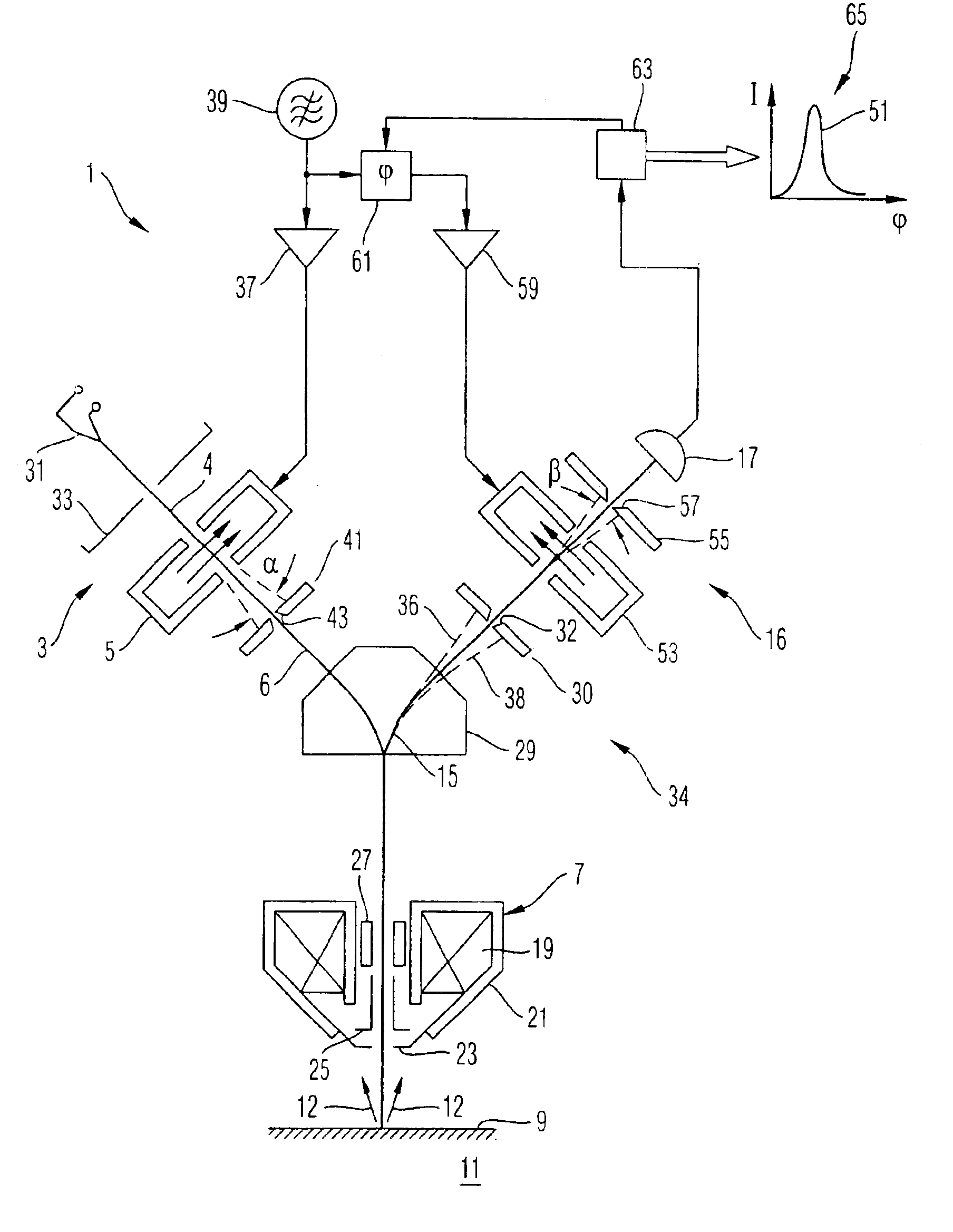
[0061]An electron microscopy system 1 shown schematically in FIG. 1 comprises an electron beam source 3 for generating a primary electron beam 6 and an objective lens 7 for focusing the primary electron beam 6 onto a surface of a sample 11 to be examined and arranged in an object plane 9 of the objective lens 7. The primary electron beam 6 focused onto the sample surface 9 generates secondary electrons 12 which emanate from the sample surface 9. A part of the secondary electrons 12 enters into the objective lens 7 and is shaped by same to a secondary electron beam 15, which eventually reaches an electron detector 17 of an electron det...


PUM

PropertyMeasurementUnit
time resolutionaaaaaaaaaa
energyaaaaaaaaaa
time resolutionaaaaaaaaaa

Abstract

An electron microscopy system and an electron microscopy method for detection of time dependencies of secondary electrons generated by primary electrons is provided, in which the primary electron pulses are directed onto a sample surface and electrons emanating from the sample surface are detected, time resolved. To this end the system comprises in particular a cavity resonator. A cavity resonator can also be used to reduce aberrations of focusing lenses.

Description

[0001]This application claims priority to German Patent Application No. 103 17 894.5 filed in Germany on Apr. 17, 2003, the entire contents of which are incorporated herein by reference.BACKGROUND OF THE INVENTION[0002]1. Field of the Invention[0003]The invention relates to a focusing system for charged particles, an electron microscopy system and an electron microscopy method.[0004]2. Brief-Description of Related Art[0005]In a conventional electron microscopy system and method, a primary electron beam is directed onto a sample to be inspected. The electrons impinging on the sample react with the sample and cause emanance of electrons from the sample. These electrons emanating from the sample are then detected. According to the characteristics of the sample at the position at which the primary electron beam impinges thereupon, more or less electrons will, at constant primary electron beam intensity, emanate from the sample. From an examination of the intensity of the electrons emana...

Claims


Application Information

Patent Timeline
Patent Type & Authority Patents(United States)
IPC IPC(8): H01J37/153H01J37/28H01J37/04H01J37/12H01J37/05H01J37/10G01Q30/02
CPCH01J37/05H01J37/12H01J37/153H01J37/28
Inventor STEIGERWALD, MICHAELESSERS, ERIK
Owner CARL ZEISS AG
Why Eureka
Try Eureka