Integrated method and device for a dual stage micro-actuator and suspension design for the hard disk driver

a micro-actuator and suspension technology, applied in the direction of maintaining head carrier alignment, recording information storage, instruments, etc., can solve the problems of micro-actuator more vulnerable to shock, weakening its structure, and reducing effectiveness

Inactive Publication Date: 2005-09-27
SAE MAGNETICS (HK) LTD
View PDF6 Cites 61 Cited by
  • Summary
  • Abstract
  • Description
  • Claims
  • Application Information

AI Technical Summary

Problems solved by technology

Distortion of the micro-actuator can weaken its structure, reducing effectiveness and making the micro-actuator more vulnerable to shocks.
Distortion can also increase the likelihood of particle generation.

Method used


Image

  • Integrated method and device for a dual stage micro-actuator and suspension design for the hard disk driver
  • Integrated method and device for a dual stage micro-actuator and suspension design for the hard disk driver
  • Integrated method and device for a dual stage micro-actuator and suspension design for the hard disk driver

Examples


Embodiment Construction

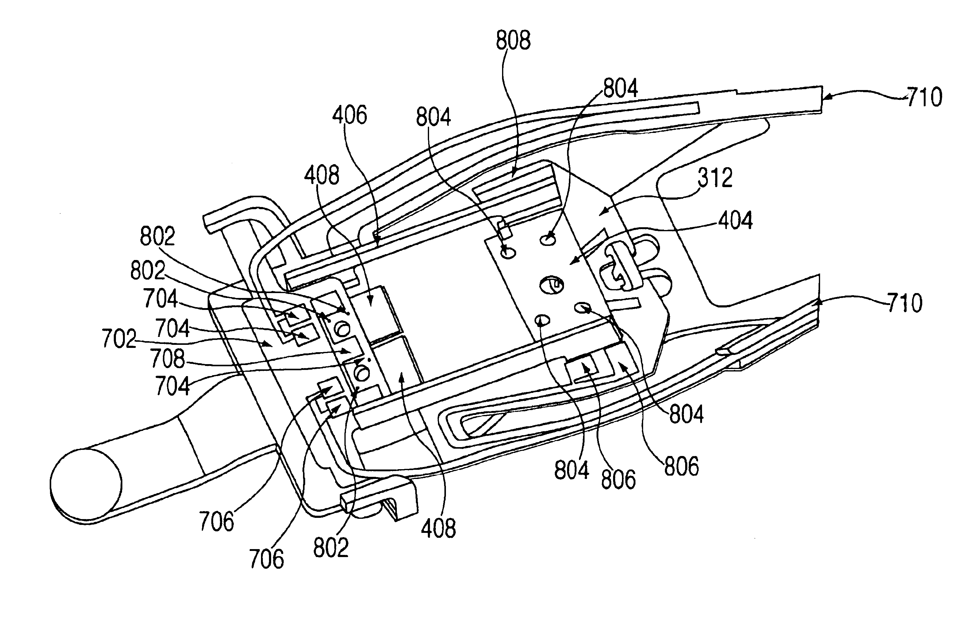
[0017]A system and method is described using a connection plate to electrically couple a magnetic read / write head to a printed circuit assembly. In one embodiment, the connection plate has a set of contact pads to control read operations and a set of contact pads to control write operations. In a further embodiment, the printed circuit assembly also allows control of the micro-actuator arms. In one embodiment, the connection plate can be attached to a framing assembly of the micro-actuator by laser welding or by using an ultraviolet cured epoxy.

[0018]Illustrated in an upside-down orientation, FIG. 3a describes one embodiment of a hard disk drive head gimbal assembly (HGA) with a ‘U’-shaped micro-actuator. In one embodiment, a magnetic read / write head, or slider, 302 is coupled to a framing assembly 304 forming a ‘U’-shaped micro-actuator. In a further embodiment, the ‘U’-shaped micro-actuator has a piezoelectric Lead Zirconate Titanate, (PZT) beam (arm) 306 attached to an arm 308 on...


PUM

PropertyMeasurementUnit
thicknessaaaaaaaaaa
phaseaaaaaaaaaa
piezoelectricaaaaaaaaaa

Abstract

A system and method using a connection plate to electrically couple a magnetic read / write head to a printed circuit assembly. The connection plate has a set of contact pads to control reads and a set of contact pads to control. The printed circuit assembly also allows control of the micro-actuator arms. The connection plate can be attached to a framing assembly of the micro-actuator by laser welding or by using an ultraviolet cured epoxy.

Description

BACKGROUND INFORMATION[0001]The present invention relates to magnetic hard disk drives. More specifically, the present invention relates to a method of electrically coupling a slider to a head arm assembly.[0002]In the art today, different methods are utilized to improve recording density of hard disk drives. FIG. 1 provides an illustration of a typical disk drive with a drive arm 102 configured to read from and write to a magnetic hard disk 104. Often, voice-coil motors (VCM) 106 are used for controlling a hard drive's arm 102 motion across a magnetic hard disk 106. Because of the inherent tolerance (dynamic play) that exists in the placement of a recording head 108 by a VCM 106 alone, micro-actuators 110 are now being utilized to ‘fine-tune’ head 108 placement. A VCM 106 is utilized for course adjustment and the micro-actuator 110 then corrects the placement on a much smaller scale to compensate for the VCM's 106 (with the arm 102) tolerance. This enables a smaller recordable trac...

Claims


Application Information

Patent Timeline
Patent Type & Authority Patents(United States)
IPC IPC(8): G11B5/55
CPCG11B5/5552
Inventor YAO, MING GAOSHIRAISHI, MASASHIXIE, YI RU
Owner SAE MAGNETICS (HK) LTD
Why Eureka
Try Eureka