Arrangement for searching packet policies using multi-key hash searches in a network switch

a network switch and policy search technology, applied in the direction of data switching networks, digital transmission, electrical equipment, etc., can solve the problems of imposing a substantial burden on affecting and affecting the performance of layer b>3/b> processing, etc., to achieve the effect of maintaining flexibility for programming and improving the speed of search operation

Inactive Publication Date: 2005-09-27
GLOBALFOUNDRIES INC
View PDF18 Cites 125 Cited by
  • Summary
  • Abstract
  • Description
  • Claims
  • Application Information

AI Technical Summary

Benefits of technology

[0015]One aspect of the present invention provides a method in a network switch of searching for a selected layer 3 switching entry for a received data packet. The method includes generating first and second hash keys according to a prescribed hash function in response to first and second layer 3 information within the received data packet, respectively, combining the first and second hash keys according to a prescribed combination into a signature for the received data packet, and searching a table. The table is configured for storing layer 3 signatures that index respective layer 3 switching entries according to the prescribed hash function and the prescribed combination. The table is searched for the selected layer 3 switching entry based on a match between the corresponding layer 3 signature and the signature for the received data packet. Generation of the signature from at least two hash keys for searching of the table enables search operations, normally requiring multiple key searches, to be reduced in hardware to a single search operation, dramatically improving the speed of the search operation. Moreover, the generation of the hash keys using first and second layer 3 information enables layer 3 processing to be performed in real time in a network switch, while maintaining flexibility for programming of the layer 3 switch by searching the layer 3 signatures that index the layer 3 switching entries.
[0016]Another aspect of the present invention provides a method of identifying a layer 3 switching decision within an integrated network switch having a plurality of network ports and switching logic. The method includes storing, in a first table, layer 3 switching entries that identify data packet types based on layer 3 information, respectively, each layer 3 switching entry identifying a corresponding layer 3 switching decision to be performed by the integrated network switch. An entry signature is generated for each of the layer 3 switching entries based on a prescribed hash operation performed on first and second portions of the corresponding layer 3 information. The method also includes generating a packet signature by a network port for a data packet at the network port based on performing the prescribed hash operation on the first and second portions of the layer 3 information in the corresponding received data packet. The network port identifies one of the layer 3 switching entries for switching of the received data packet based on detecting a match between the packet signature and the corresponding entry signature. Generation of the entry signature based on portions of the layer 3 information for each corresponding layer 3 switching entry enables a single key to be used for searching for the appropriate layer 3 switching entry by a network switch port. Hence, the identification of the layer 3 switching entry by the network switch port provides distributed processing, enabling the switching logic to perform layer 3 switching operations in real time.

Problems solved by technology

However, such design requirements risk loss of the non-blocking features of the network switch, as it becomes increasingly difficult for the switching fabric of a network switch to be able to perform layer 3 processing at the wire rates (i.e., the network data rate).
Hence, the number of such user policies may be very large, posing a substantial burden on performance of layer 3 processing at the wire rates.

Method used


Image

  • Arrangement for searching packet policies using multi-key hash searches in a network switch
  • Arrangement for searching packet policies using multi-key hash searches in a network switch
  • Arrangement for searching packet policies using multi-key hash searches in a network switch

Examples


Embodiment Construction

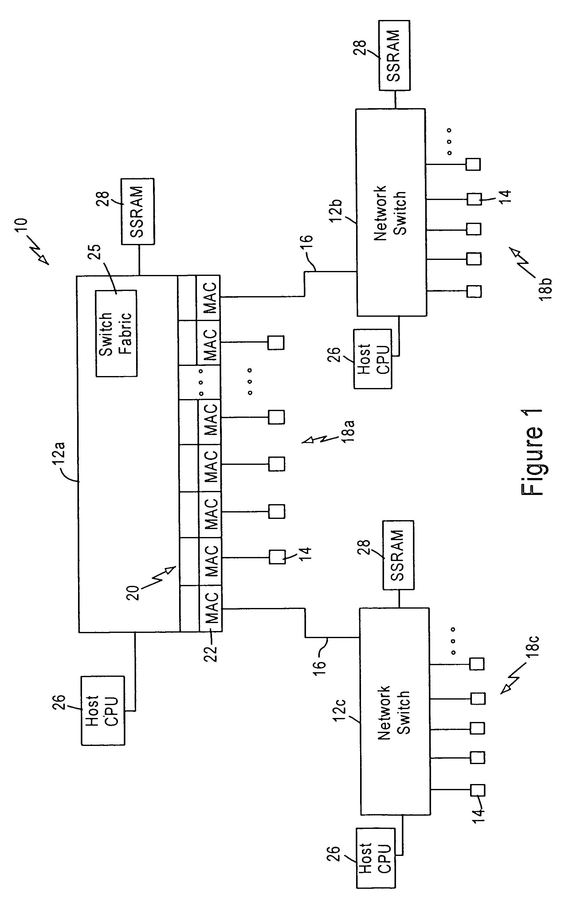
[0024]FIG. 1 is a block diagram illustrating a packet switched network 10, such as an Ethernet (IEEE 802.3) network. The packet switched network includes integrated (i.e., single chip) multiport switches 12 that enable communication of data packets between network stations 14. Each network station 14, for example a client workstation, is typically configured for sending and receiving data packets at 10 Mbps or 100 Mbps according to IEEE 802.3 protocol. Each of the integrated multiport switches 12 are interconnected by gigabit Ethernet links 16, enabling transfer of data packets between subnetworks 18a, 18b, and 18c. Hence, each subnetwork includes a switch 12, and an associated group of network stations 14.

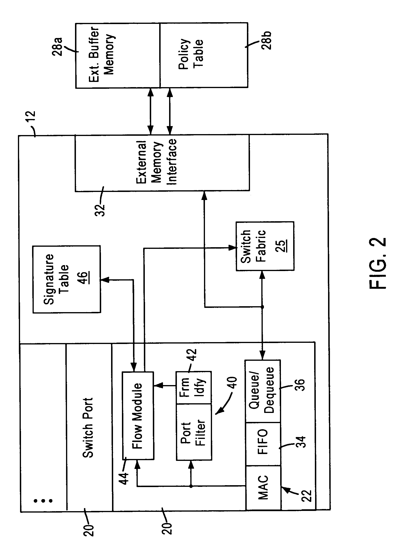
[0025]Each switch 12 includes a switch port 20 that includes a media access control (MAC) module 22 that transmits and receives data packets to the associated network stations 14 across 10 / 100 Mbps physical layer (PHY) transceivers (not shown) according to IEEE 802.3u protocol. Ea...


PUM


Abstract

A network switch, configured for performing layer 2 and layer 3 switching in an Ethernet (IEEE 802.3) network without blocking of incoming data packets, includes network switch ports, each including a flow module configured for generating a packet signature based on layer 3 information within a received data packet. The flow module generates first and second hash keys according to a prescribed hashing function upon obtaining first and second portions of layer 3 information. The flow module combines the first and second hash keys to form the packet signature, and searches an on-chip signature table that indexes addresses of layer 3 switching entries by entry signatures, where the entry signatures are generated using the same prescribed hashing function on the first and second layer 3 portions of the layer 3 switching entries.

Description

[0001]This application claims priority from Provisional Application No. 60 / 169,296, filed Dec. 7, 1999.BACKGROUND OF THE INVENTION[0002]1. Field of the Invention[0003]The present invention relates to layer 2 and layer 3 switching of data packets in a non-blocking network switch configured for switching data packets between subnetworks.[0004]2. Background Art[0005]Local area networks use a network cable or other media to link stations on the network. Each local area network architecture uses a media access control (MAC) enabling network interface devices at each network node to access the network medium.[0006]The Ethernet protocol IEEE 802.3 has evolved to specify a half-duplex media access mechanism and a full-duplex media access mechanism for transmission of data packets. The full-duplex media access mechanism provides a two-way, point-to-point communication link between two network elements, for example between a network node and a switched hub.[0007]Switched local area networks a...

Claims


Application Information

Patent Timeline
Patent Type & Authority Patents(United States)
IPC IPC(8): H04L12/56H04L12/28
CPCH04L49/3009H04L49/351H04L49/602
Inventor VISWANATH, SOMNATHKRISHNA, GOPAL
Owner GLOBALFOUNDRIES INC
Why Eureka
Try Eureka