
Packet transmission system in which packet is transferred without replacing address in the packet

Inactive Publication Date: 2005-09-27
SOCIONEXT INC
View PDF4 Cites 10 Cited by
  • Summary
  • Abstract
  • Description
  • Claims
  • Application Information

AI Technical Summary

Benefits of technology

[0034]An object of the present invention is to provide a packet transmission system in which the processing speed is not decreased, and hardware resources are not required to be increased.
[0035]Another object of the present invention is to provide a host apparatus used in a packet transmission system, which contributes to prevention of decrease in the processing speed and increase in hardware resources in the packet transmission system.
[0036]A further object of the present invention is to provide a router apparatus used in a packet transmission system, which contributes to prevention of decrease in the processing speed and increase in hardware resources in the packet transmission system.

Problems solved by technology

Thus, the cost of the router 14 increases.
However, regardless of whether the functions of the above processing is realized by hardware or software, the manufacturing cost of the router increases, and the packet transfer rate decreases.

Method used


Image

  • Packet transmission system in which packet is transferred without replacing address in the packet
  • Packet transmission system in which packet is transferred without replacing address in the packet
  • Packet transmission system in which packet is transferred without replacing address in the packet

Examples


Embodiment Construction

[0078]An embodiment of the present invention is explained in detail below with reference to FIGS. 1 to 10.

(1) Basic Construction

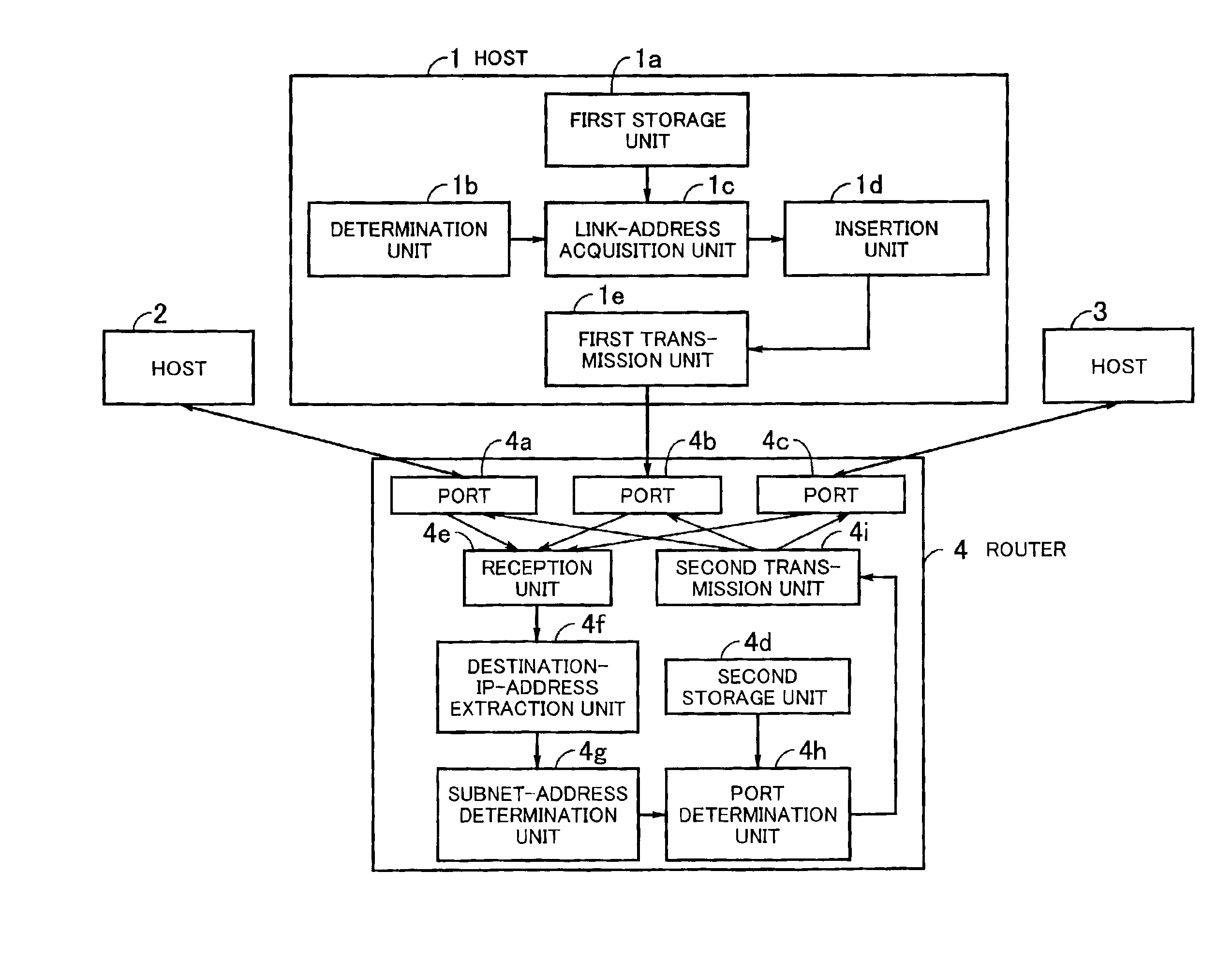
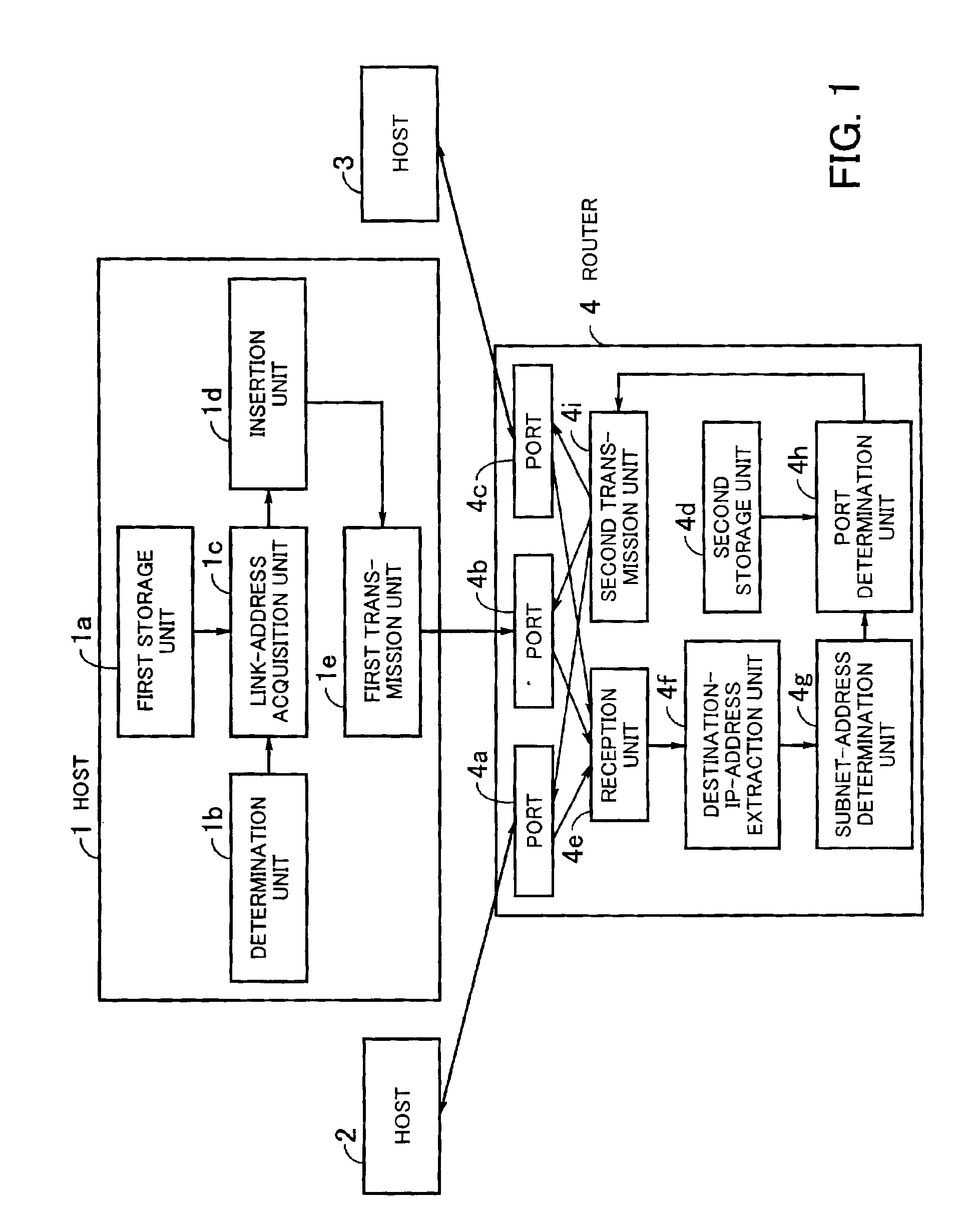
[0079]FIG. 1 is a diagram illustrating the principle of the packet transmission system according to the present invention. The network system in FIG. 1 comprises hosts 1 to 3 and a router 4. Each of the hosts 1 to 3 transmits a packet to another of the hosts 1 to 3 through the router 4, and receives a packet from another of the hosts 1 to 3 through the router 4. The router 4 receives a packet transmitted from one of the hosts 1 to 3, refers to information inserted in a header of the packet, and transfers the packet to an appropriate one of the hosts 1 to 3.

[0080]Each of the hosts 1 to 3 comprises a first storage unit 1a, a determination unit 1b, a link-address acquisition unit 1c, an insertion unit 1d, and a first transmission unit 1e.

[0081]The first storage unit 1a stores IP addresses of hosts which belong to a first subnetwork defined at a first predeter...


PUM


Abstract

In a packet transmission system including host apparatuses and a router which transfers a packet from host apparatuses in a first host group to host apparatuses in a second host group, each host apparatus in the first host group inserts in a packet an IP address and a link-layer address of a destination host apparatus in the second host group before transmitting the packet. When the router receives the packet, the router determines an output port connected to at least one host apparatus in the second host group including the destination host apparatus, based on the IP address of the destination host apparatus inserted in the packet, and transmits the received packet from the determined output port.

Description

BACKGROUND OF THE INVENTION[0001]1) Field of the Invention[0002]The present invention relates to a packet transmission system for transmitting a packet between hosts through a router. The present invention also relates to a router and a host used in such a packet transmission system. The present invention further relates to a semiconductor device which is used in the router for realizing desired functions in the router.[0003]2) Description of the Related Art[0004]As a result of the recent progress in computerization, LANs (Local Area Networks) have been constructed in a great number of companies, regardless of their size. Further, since the Internet has been rapidly popularized, home use of LANs is spreading.[0005]When LANs are constructed, devices for transferring packets, such as hubs, L2 (layer 2) switches, routers, and L3 (layer 3) switches, are indispensable constituents of the LANs. In particular, hubs and L2 switches are used only inside respective LANs. The hub is such a dev...

Claims


Application Information

Patent Timeline
IPC IPC(8): H04L12/56H04L12/46H04L45/60
CPCH04L45/04
Inventor ASANO, KAZUYANAGATOMO, TERUHIKO
Owner SOCIONEXT INC
Learn More