Dual fuel burner for a shortened flame and reduced pollutant emissions

a dual fuel burner and flame length technology, applied in the direction of combustion types, combustion using lump and pulverulent fuel, lighting and heating apparatus, etc., can solve the problems of reducing the efficiency of combustion, adding a substantial level of undesirable complexity, and spuds are difficult to fit in the burner, so as to reduce the length of flames and co emissions, reduce the effect of co and nox emissions and short flames

Inactive Publication Date: 2005-10-04
THE BABCOCK & WILCOX CO
View PDF31 Cites 50 Cited by
  • Summary
  • Abstract
  • Description
  • Claims
  • Application Information

AI Technical Summary

Benefits of technology

[0011]It is therefore an object of the present invention to provide a gaseous fuel injector for a burner, which simultaneously produces short flames and low CO and NOx emissions via unique drilling patterns. The gas injector is connected to a supply pipe extending to the burner opening at the furnace wall. The drilling pattern in the injector imparts a swirling action to the gaseous fuel jets as they emerge from the discharge holes. Mixing between the gaseous fuel and air is improved relative to non-swirling fuel jets, resulting in significant reductions in the flame length and CO emissions, and NOx emissions comparable to other single gas injectors.
[0013]It is another object of the invention to provide a burner assembly designed to fire both gas and pulverized coal and having a gas injector that is easier to fit in the burner without interference with the coal nozzle and elbow assembly.
[0014]It is yet another object of the invention to provide a burner assembly designed to fire both gas and pulverized coal and having a gas injector that is easily retracted for protection from heat and slag during coal-only firing.

Problems solved by technology

As can be seen in FIGS. 1A, 1B and 1C, these three burner arrangements all employ a common manifold to distribute the natural gas among a multitude of gas spuds, adding a substantial level of undesirable complexity.
Undesirable complexity is further compounded in burners designed to fire both gas and pulverized coal, either alone or in combination, using multiple axial gas spuds.
The spuds are difficult to fit in the burner without interference with the coal nozzle and elbow assembly, and are not easily retracted for protection from heat and slag during coal-only firing.
While these levels of NOx, CO and flame length are presently acceptable, this arrangement, as noted above, is mechanically complex.
Nevertheless, despite the significantly lower NOx emissions, natural gas injection through a single centerline super spud has resulted in long flame lengths.
These longer flames can impinge on the opposite walls of shallow depth boilers or furnaces, resulting in poor heat absorption and deterioration of combustion.

Method used


Image

  • Dual fuel burner for a shortened flame and reduced pollutant emissions
  • Dual fuel burner for a shortened flame and reduced pollutant emissions
  • Dual fuel burner for a shortened flame and reduced pollutant emissions

Examples


Embodiment Construction

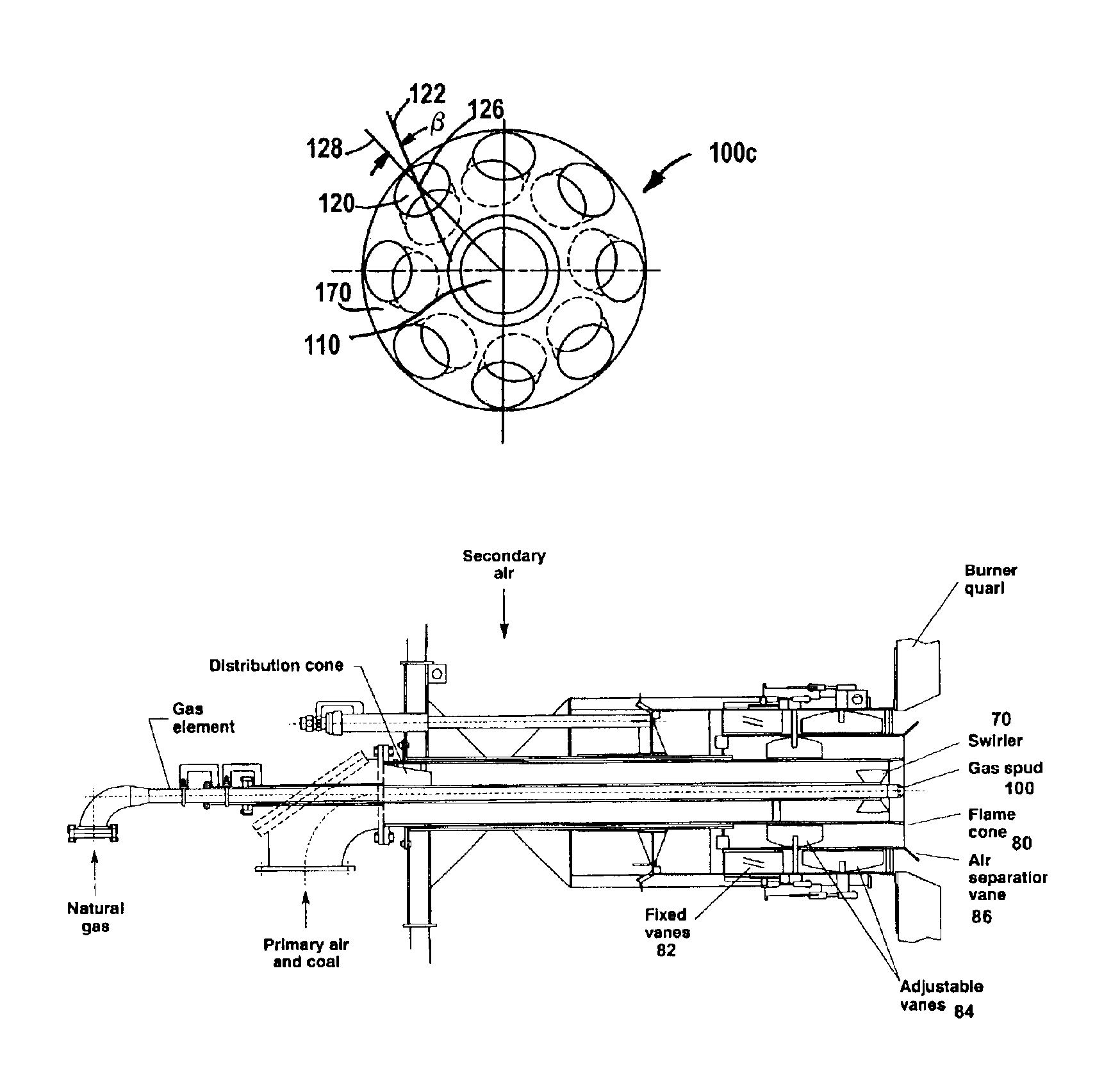
[0029]Referring now to the drawings, in which like reference numerals are used to refer to the same or similar elements, FIG. 2 shows part of a boundary wall 12 of a furnace and a burner 10 having a gaseous fuel supply pipe 50 formed with an inlet end 14 and an outlet end 16, and a gas injector element 100 attached to the outlet end 16 and extending into the furnace wall burner opening or port 40 as defined by the burner throat 30. A first sleeve member 62 is concentrically spaced about the supply pipe 50 and the injector 100 to form an inner annular passageway 57 for conveying a mixture of air and pulverized coal to the combustion zone 20. A second sleeve member 63 is concentrically spaced about the first sleeve member 62 to form an outer annular passageway 67 for conveying secondary air 59 to the combustion zone 20. The secondary air stream 59 for combustion flows into the outer annular passageway 67 which is provided with swirl vanes 72 for distribution and mixing of air with com...


PUM


Abstract

A dual fuel burner including an elongated supply pipe and a gas injector for a boiler furnace having a plurality of peripheral openings around a center opening. The peripheral openings are pitched radially away from the longitudinal axis of the gas injector and also pitched either clockwise or counter-clockwise, to impart a swirling motion to gaseous fuel exiting the injector through the openings. A first sleeve member is concentrically spaced about the supply pipe and the gas injector to form an inner annular passageway for conveying a mixture of primary air and pulverized coal to the furnace combustion zone. A second sleeve member is concentrically spaced about the first sleeve member to form an outer annular passageway for conveying secondary air to the furnace combustion zone, and a plurality of circumferentially spaced vanes mounted within the outer annular passageway for inducing a swirling motion to the secondary air discharging from the outer annular passageway into the furnace combustion zone.

Description

FIELD AND BACKGROUND OF THE INVENTION[0001]The present invention relates generally to the field of commercial and industrial power generation, and in particular to a new and useful injector for gas-fired burners used in furnaces.[0002]There are four main methods for firing natural gas in large-scale, commercial fossil fueled burners. Two of these methods, depicted in FIGS. 1A and 1B, contemplate a plurality of separate, equally spaced natural gas injection nozzles (spuds) mounted in the swirling air zones near the burner exit. In a third method, multiple longitudinal spuds are arranged in a circular array, as shown in FIG. 1C. As can be seen in FIGS. 1A, 1B and 1C, these three burner arrangements all employ a common manifold to distribute the natural gas among a multitude of gas spuds, adding a substantial level of undesirable complexity. The burner arrangements of FIGS. 1A and 1B also require the spuds to be placed in fixed positions in the air zones. Notably, each individual spud ...

Claims


Application Information

Patent Timeline
Patent Type & Authority Patents(United States)
IPC IPC(8): F23D1/00F23D14/46F23D14/24F23D17/00F23D14/84F23D14/00
CPCF23D1/00F23D14/24F23D14/84F23D17/005
Inventor SARV, HAMIDLENZER, RONALD C.
Owner THE BABCOCK & WILCOX CO
Why Eureka
Try Eureka