

Transmission actuator
a technology of transmission actuator and actuator, which is applied in the direction of mechanical actuation clutch, transportation and packaging, etc., can solve the problems of increasing mass and inertia moment, limiting the mounting position of the motor, and occupying less space, so as to achieve good transmission power response and less space occupied
- Summary
- Abstract
- Description
- Claims
- Application Information
AI Technical Summary
Benefits of technology
Problems solved by technology
Method used
Image

Examples
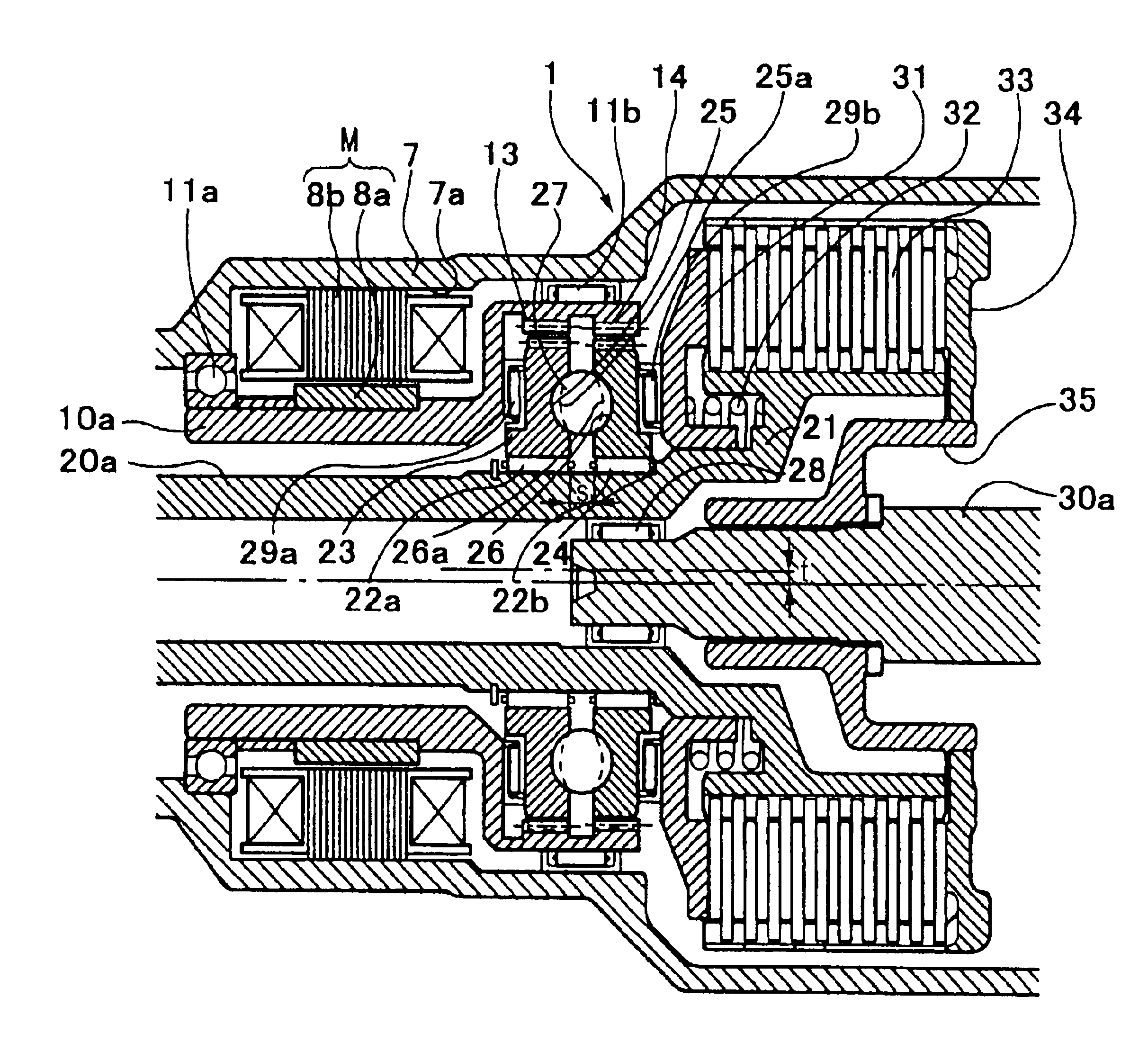
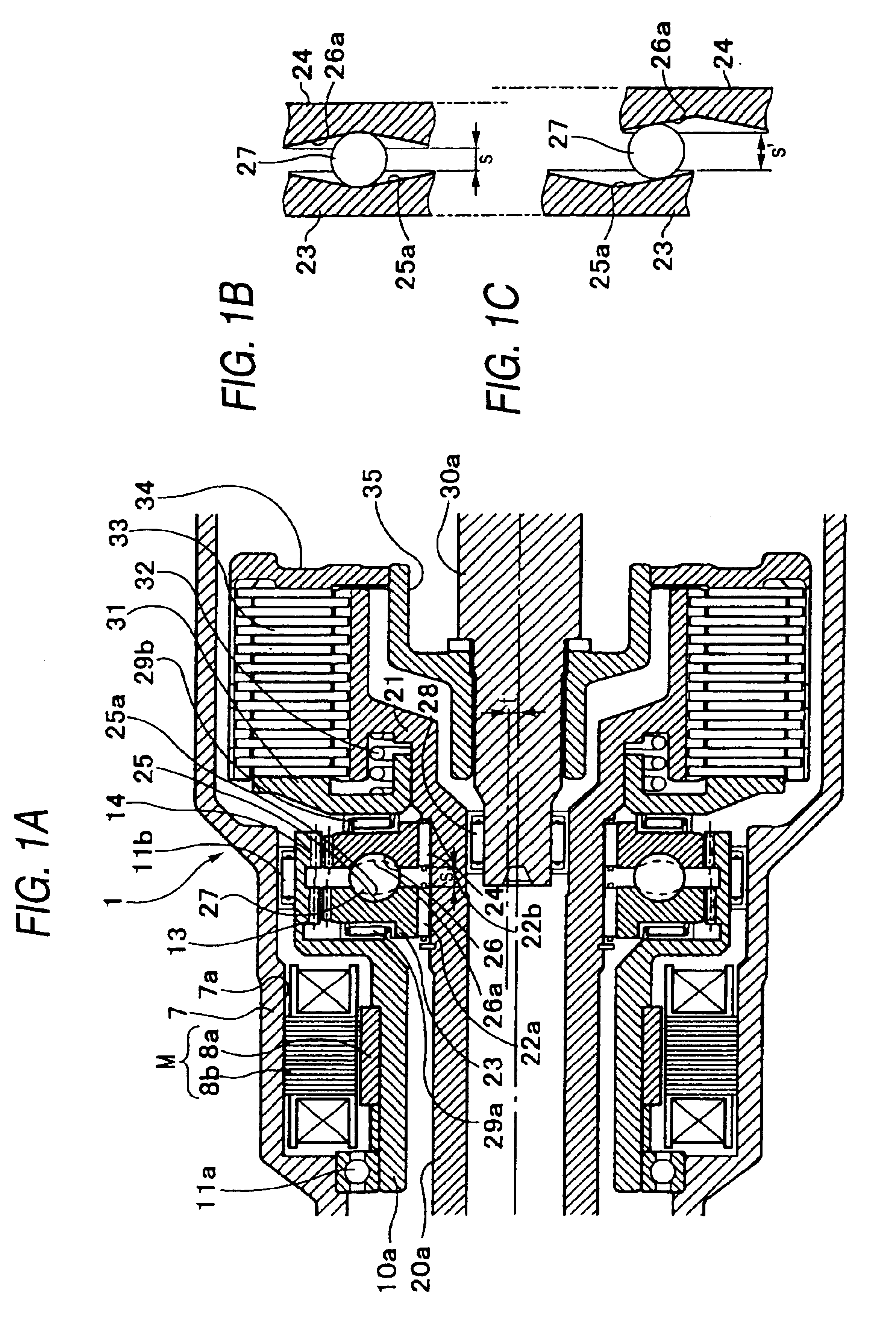
first embodiment
[0046]What is different from the first embodiment is that the positions of a motor and internally toothed gears formed by diametrically expanding a drive shaft are longitudinally reversed.
second embodiment
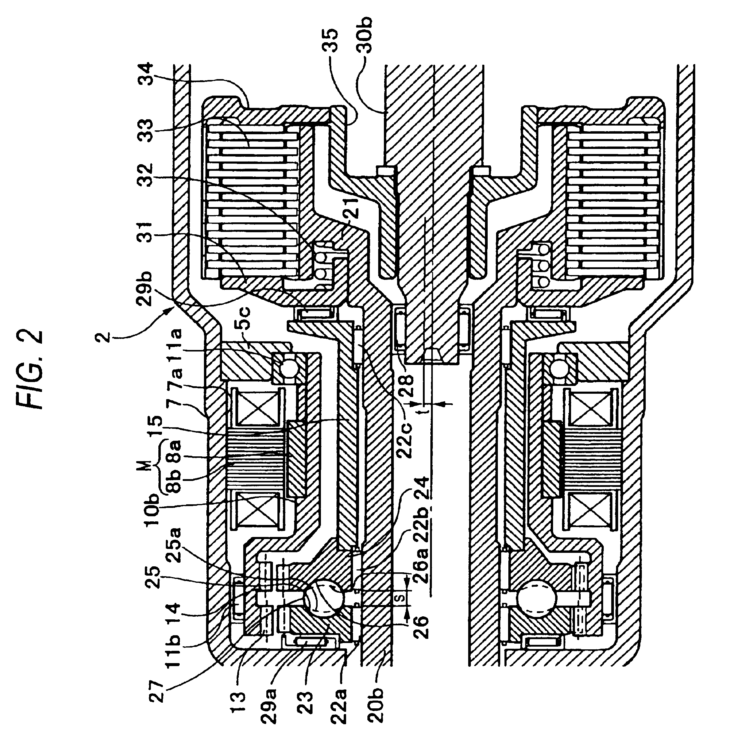
[0047]FIG. 2 is a sectional view illustrating a transmission actuator according to the invention.
[0048]Note that in a transmission actuator 2 shown in FIG. 2, like reference numerals are imparted to like components to those illustrated in FIG. 1A, and a detailed description thereof will be omitted.
[0049]As shown in FIG. 2, the transmission actuator 2 includes a torque generating mechanism, a speed reduction gear, a motion direction changing mechanism and a friction engagement mechanism.
[0050]The torque generating mechanism is a built-in motor M and comprises a rotor 8a fixedly fitted on an outer circumferential surface of a right end of a hollow drive shaft 10b and a stator 8b fixed fitted in an inner circumferential surface 7a of a case 7. The right end of the hollow drive shaft 10b is rotatably supported by a bearing 11a on the case 7 via a retainer 5c, a left end of the hollow shaft 10b which is diametrically expanded is rotatably supported by a bearing 11b disposed between an ou...
third embodiment
[0077]Since descriptions of the motion direction changing mechanism and the friction engagement mechanism overlap those made in the third embodiment, descriptions thereof will be omitted here.
[0078]Next, the operation of the transmission actuator 4 will be described.
[0079]As shown in FIG. 4, once an activating signal enters the motor M which is built in the torque generating mechanism, the motor M rotates the rotor 8a fixedly fitted on the hollow drive shaft 10d, as well as the drive shaft 10d which is made integral with the rotor 8a. Then, the first externally toothed gear 23 formed on the outer circumferential surface of the flange-like formed right end of the drive shaft 10d is rotated concentrically relative to the input shaft 20d. Since the first pinion gear 43 and the second pinion gear 44 are formed integrally on the pinion 42, the second pinion gear 44 transmits torque (rotational force) to the second externally toothed gear 24. As a result, since the numbers of teeth of the...
PUM
 Abstract
Description
Claims
Application Information