Percutaneous myocardial revascularization device and method

a myocardial revascularization and percutaneous technology, applied in the field of percutaneous myocardial revascularization devices and methods, can solve the problems of no longer being able to contract and difficult to restore blood flow to the heart muscle, and achieve the effect of reducing the movement of the beating heart wall and reducing the movement of the heart wall

Inactive Publication Date: 2005-10-04
BOSTON SCI SCIMED INC
View PDF57 Cites 27 Cited by
  • Summary
  • Abstract
  • Description
  • Claims
  • Application Information

AI Technical Summary

Benefits of technology

[0010]Yet another method can be accomplished by providing a myocardial channel forming device having an anchoring member, a treatment member with a cutting tip, means for rotating the cutting member about the anchoring member, and means for controlling the radial displacement of the cutting tip from the anchoring member. The anchoring member can be implanted in a heart chamber wall using a pigtail, and the radial and rotational displacement of the cutting tip controlled to sequentially form a circular cluster of channels about the anchoring member. The circular cluster preferably includes both healthy and hibernating tissue areas, which can be mapped using conventional techniques. A variant of this technique utilizes a device having a spline and corresponding star shaft, which restricts the number of possible rotational angles and provide predictable arc rotations around the spline for the treatment member about the anchoring shaft.
[0011]Still another method utilizes a bundle of fibers within a sheath as the cutting device. Preferred fibers are formed of Nitinol wire and carry radio frequen...

Problems solved by technology

In some patients, the number of lesions are so great, or the location so remote in the patient vasculature that restoring blood flow to the heart musc...

Method used


Image

  • Percutaneous myocardial revascularization device and method
  • Percutaneous myocardial revascularization device and method
  • Percutaneous myocardial revascularization device and method

Examples


Embodiment Construction

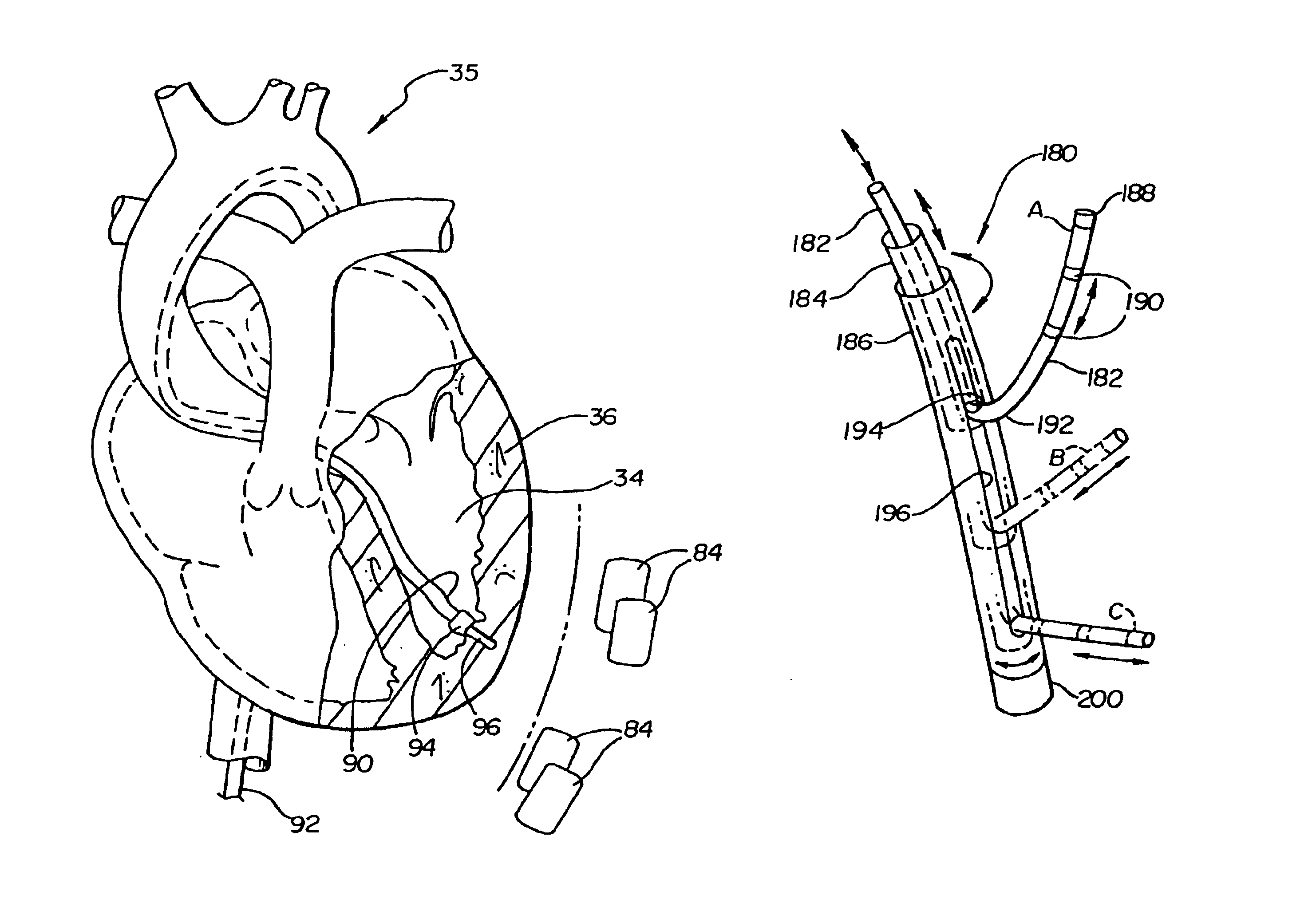
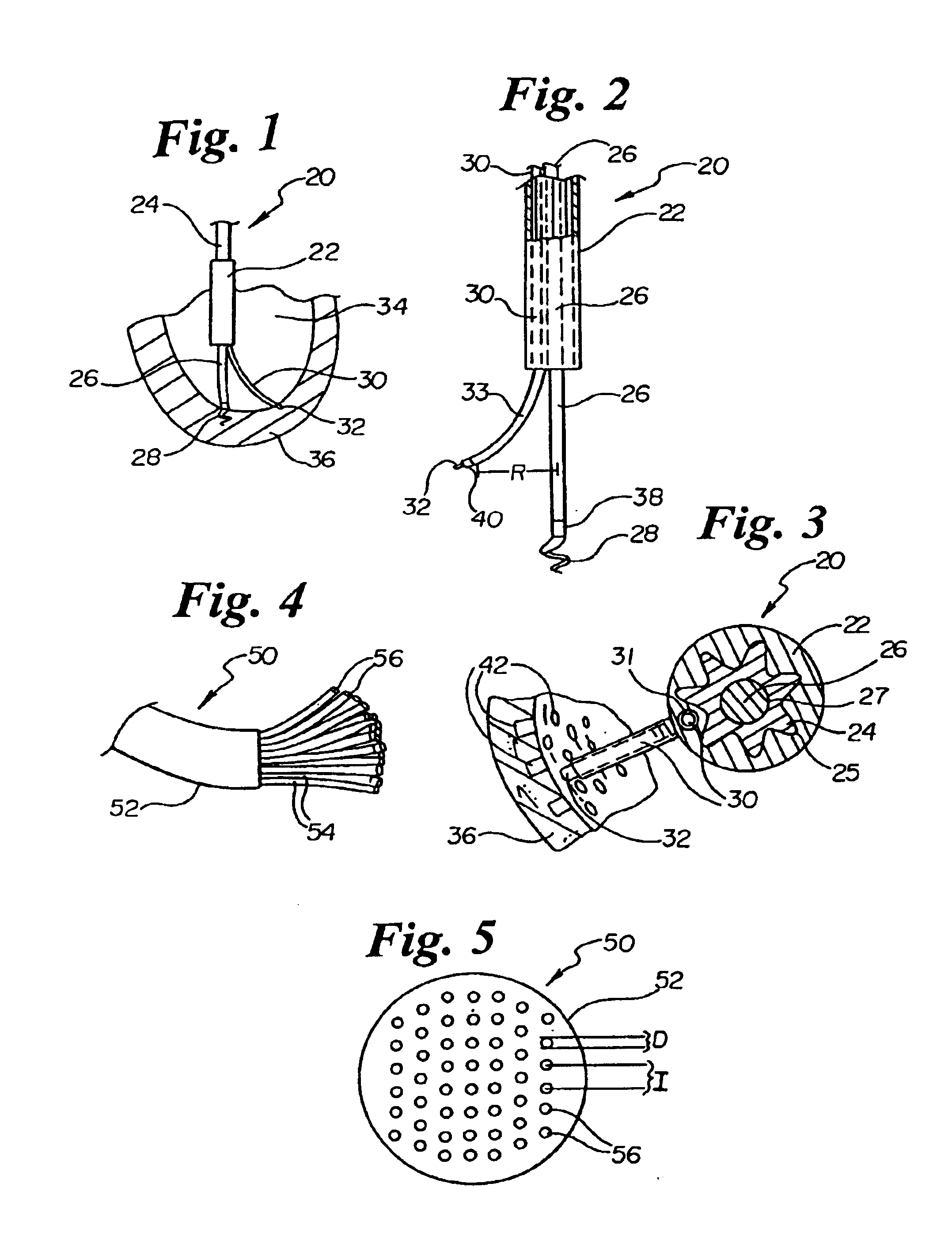
[0038]FIG. 1 illustrates an anchorable percutaneous myocardial revascularization (PMR) treatment catheter 20 disposed within a left ventricle 34. PMR catheter 20 includes an inner star shaft 24 disposed within an outer catheter shaft 22, an anchoring shaft 26 disposed within star shaft 24, and a treatment shaft or probe 30 disposed within catheter shaft 22. Catheter shaft 22 has been cut away proximally in FIG. 1, illustrating inner star shaft 24 within. Anchoring shaft 26 has an anchor 28 disposed at the distal end. In a preferred embodiment, anchor 28 has a pigtail or corkscrew configuration, capable of reversibly securing itself to the ventricular wall through rotation of anchoring shaft 26. One embodiment anchor includes a distal barb, capable of securing itself to the ventricular wall through translation of anchoring shaft 26, not requiring shaft rotation for anchoring. In another embodiment, anchoring shaft 26 includes a vacuum lumen therethrough terminating in a distal orific...


PUM


Abstract

Devices and methods for creating a series of percutaneous myocardial revascularization (PMR) channels in the heart. One method includes forming a pattern of channels in the myocardium leading from healthy tissue to hibernating tissue. Suitable channel patterns include lines and arrays. One method includes anchoring a radiopaque marker to a position in the ventricle wall, then using fluoroscopy repeatedly to guide positioning of a cutting tip in the formation of multiple channels. Another method uses radiopaque material injected into each channel formed, as a marker. Yet another method utilizes an anchorable, rotatable cutting probe for channel formation about an anchor member, where the cutting probe can vary in radial distance from the anchor. Still another method utilizes a multiple wire radio frequency burning probe, for formation of multiple channels simultaneously. Still another method utilizes liquid nitrogen to cause localized tissue death.

Description

CROSS REFERENCE TO RELATED APPLICATION[0001]The present application is a Continuation of application Ser. No. 09 / 536,068 which was filed on Mar. 24, 2000, now U.S. Pat. No. 6,491,689, which is a division of application Ser. No. 09 / 035,625 filed Mar. 5, 1998, now U.S. Pat. No. 6,056,743, and claims the benefit of U.S. Provisional Patent Application No. 60 / 064,169, filed Nov. 4, 1997.FIELD OF THE INVENTION[0002]The present application is related to devices and methods for promoting blood circulation to the heart muscle. Specifically, the present invention is related to percutaneous myocardial revascularization (PMR) devices and methods for forming multiple channels in the myocardium.BACKGROUND OF THE INVENTION[0003]A number of techniques are available for treating cardiovascular disease such as cardiovascular by-pass surgery, coronary angioplasty, laser angioplasty and atherectomy. These techniques are generally applied to by-pass or open lesions in coronary vessels to restore and inc...

Claims


Application Information

Patent Timeline
IPC IPC(8): A61B17/22A61B18/14A61B19/00A61B17/34A61B17/00A61B6/00A61B17/32A61B18/00A61B18/02A61B18/12
CPCA61B17/3207A61B18/1492A61B19/54A61B2017/00247A61B2017/22077A61B2017/3488A61B2018/00273A61B2018/00291A61B2018/00392A61B2018/144A61B2019/545A61M2210/125A61B90/39A61B2090/395
Inventor ELLIS, LOUISLAFONTAINE, DANIEL M.HASTINGS, ROGER N.DEVORE, LAURI
Owner BOSTON SCI SCIMED INC
Why Eureka
Try Eureka