

Method for treating a medium with ultrasonic transducers
- Summary
- Abstract
- Description
- Claims
- Application Information
AI Technical Summary
Benefits of technology
Problems solved by technology
Method used
Image

Examples
Embodiment Construction
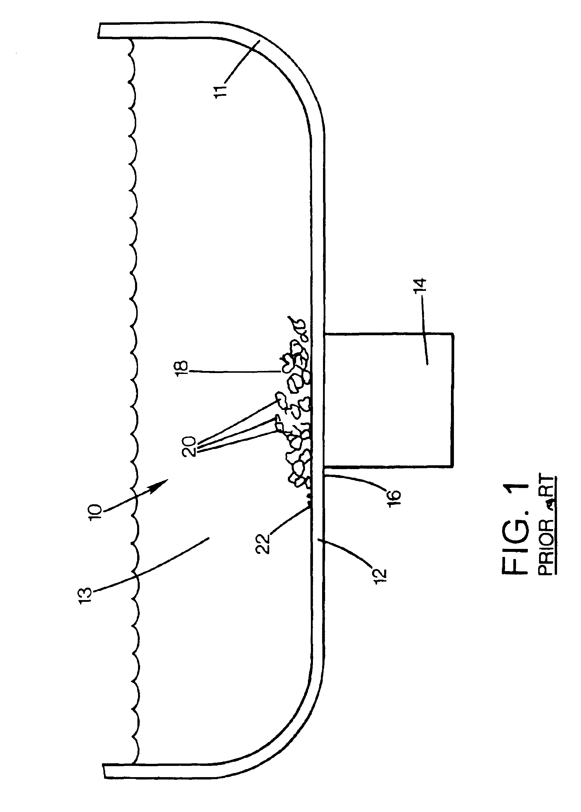
[0024]FIG. 1 is a side view of a prior art transducer system 10 that has a container 11, such as a stainless reactor, with a wall 12 for containing a liquid 13. A transducer 14 is attached to an outside 16 of the wall 12. When the transducer 14 is activated, a pillow 18 of cavitation bubbles 20 are formed on an inside 22 of the wall 12 due to the fracture zone in the liquid 13 that may be a result of fracture impressions on the inside 22 of the wall 12. The bubbles may be held to the inside wall due to the surface tension of the liquid 13. The bubbles 20 are good insulators and prevent the effective transmission of the ultrasonic energy into the liquid 13. The under-pressure pulses of the ultrasonic energy transmitted by the transducer 14 create the cavitation bubbles. In this way, the pressure inside the bubbles is very low.
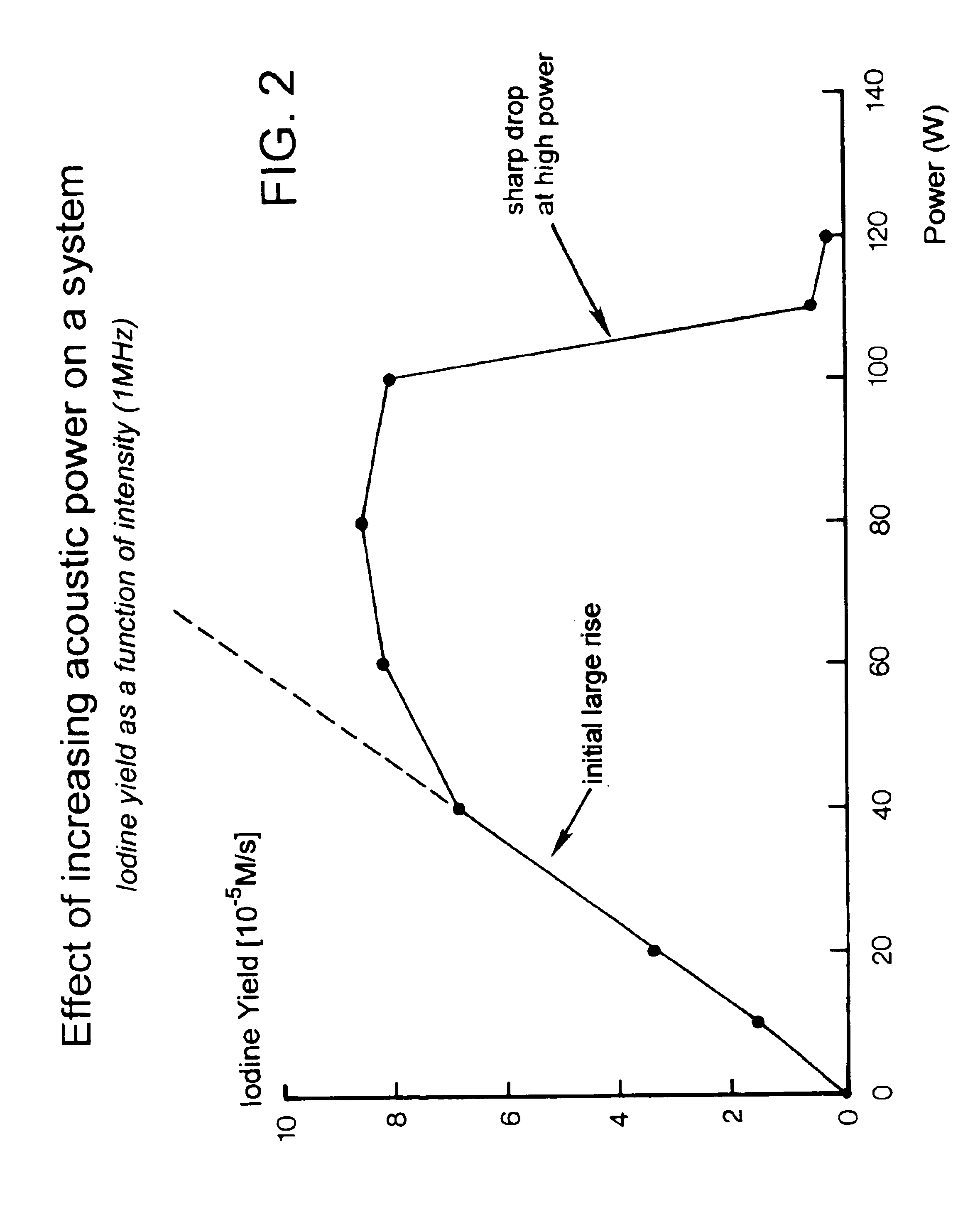
[0025]FIG. 2 is a graphical illustration that shows the iodine yield is affected by increased acoustic power on the system 10. The more power is applied, the th...
PUM
 Abstract
Description
Claims
Application Information