Efficient scenery object rendering

a technology of scenery object and rendering method, applied in the direction of image generation, using reradiation, instruments, etc., can solve the problems of not being very realistic, 2d backgrounds can have much more complex and varied textures, and simple backgrounds are only two-dimensional (2d)

Inactive Publication Date: 2005-10-04
MICROSOFT TECH LICENSING LLC
View PDF8 Cites 26 Cited by
  • Summary
  • Abstract
  • Description
  • Claims
  • Application Information

AI Technical Summary

Benefits of technology

[0009]The present invention is directed to a method and system for determining when to render a particular graphic object within one of a plurality of visual tiles in an electronic simulation, so that the rendering is efficient and more realistically portrays what an observer would expect to see as the distance decreases between the graphic objects and an observer's viewpoint. The determination is made as a function of a distance between the visual tile and the viewpoint in the electronic simulation. Graphic objects associated with the visual tile are pseudo-randomly associated with a plurality of different distance ranges such that fewer of the graphic objects are rendered when the visual tile is far from the viewpoint, and more of the graphic objects are rendered when the visual tile is closer to the viewpoint. Rendering of the graphic objects is initially triggered when the visual tile comes within a predetermined distance of the viewpoint. Additional graphic objects are then rendered as the distance decreases between the visual tile and the viewpoint. Conversely, some of the graphic objects are removed from the rendered view as the distance increases between the visual tile and the viewpoint.
[0010]Preferably, when a visual tile falls within a predefined maximum range from the viewpoint, a level of detail (LOD) value is pseudo-randomly selected for each graphic object in the visual tile and included in data defining the graphic object, which are associated with the visual tile. The LOD value indicates a maximum radial distance between the viewpoint and the visual tile at which the graphic object will be visible in the electronic simulation, i.e., a radial range of rings centered about the viewpoint within which the graphic object will be visible. Preferably, the LOD value is pseudo-randomly selected based on a seed value that is a function of the location of the visual tile in the simulation. During each frame, a current LOD value is determined for the visual tile and compared with the LOD values that were pseudo-randomly selected for each of the graphic objects in the visual tile. Graphic objects associated with the tile are rendered if they have the same LOD value as the current LOD value determined for the tile. Preferably, the graphic objects are faded into view and out of view by modulating an opacity value as the current LOD value is changing. When the current LOD value changes, the number of graphic objects that are rendered also changes, but by fading in or fading out the graphic objects over time, an abrupt change in the number of graphic objects that are rendered is avoided.
[0011]Each graphic object is preferably rendered as either a solid object with multiple adjacent surfaces (e.g., buildings) or as an orthogonal-planar object (e.g., trees or other vegetation). Textures are applied to the adjacent surfaces or orthogonal planes of these different types of objects. However, to prevent undesirable splits in the textures where surfaces adjoin, such as at a window or doorway, the textures are mapped to the size of a graphic object in increments of an integral cell size of the texture.

Problems solved by technology

Typically, these simple backgrounds are only two-dimensional (2D), and are not very realistic.
However, 2D backgrounds can have much more complex and varied textures and may be designed to be computationally efficient in covering a large area in a simulated virtual environment.
Some simulations are thus able to provide very detailed scenery objects in a limited region of the simulated environment, but because of the labor involved, the detail is confined to a relatively small area.
For instance, some automobile racing games include very detailed scenery objects that correspond to real buildings, traffic signs, trees, and other objects along some selected streets of cities in which auto races are held, but the remainder of the simulated streets of the cities lack detail and variety.
However, even with foreseeable increases in processor speeds and storage sizes, it is impractical to define, store, and render a scenery object corresponding to each real object over an extended area, such as an entire metropolitan area.
The problem becomes even more significant when the simulated environment includes the entire surface of the Earth.
However, these other products do not appear to render scenery objects in a manner that obtains the desired efficiencies described above.
However, FLY II™ does not appear to vary the number of objects rendered at various distances from a viewpoint of the user, and does not appear to provide other rendering efficiencies discussed above.

Method used


Image

  • Efficient scenery object rendering
  • Efficient scenery object rendering
  • Efficient scenery object rendering

Examples


Embodiment Construction

Exemplary Operating Environment

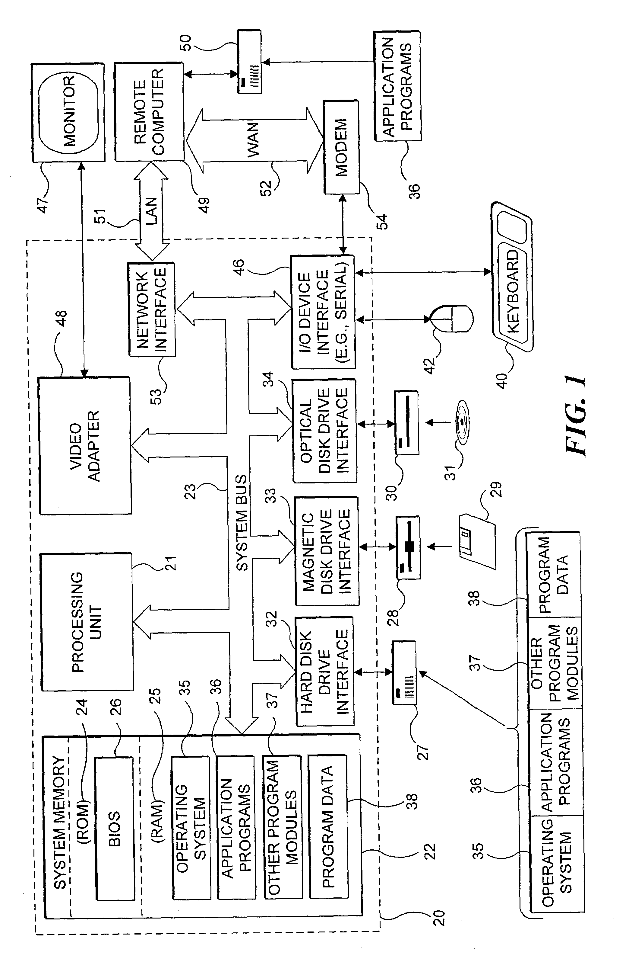
[0026]FIG. 1 and the following discussion are intended to provide a brief, general description of a suitable computing environment in which the present invention may be implemented. The invention may be practiced on a single computing device, but can also be practiced on a client computing device coupled in communication with a server and / or one or more other remote computing devices over a communication network. Both the client computing device and the server will typically each include the functional components shown in FIG. 1. Although not required, the present invention will be described in the general context of computer executable instructions, such as program modules that are executed by a PC. Generally, program modules include application programs, such as computer simulations, routines, objects, components, functions, data structures, etc. that perform particular tasks or implement particular abstract data types. Also, those skilled in the art...


PUM


Abstract

The number of graphic objects in a visual tile rendered varies as a function of distance between the tile and a viewpoint in a simulation. Fewer objects are rendered when the tile is far from the viewpoint, and vise versa. A level of detail (LOD) value is pseudo-randomly selected and associated with each object, indicating the maximum distance at which the object will be visible. A current LOD value is determined for the tile. An object is rendered if its LOD value is equal or greater than the current LOD value of the tile. Objects are faded into and out of view by modulating an opacity value as the current LOD value changes. Texture values of an object are adjusted as a function of ambient and direct components of light on the object, to achieve lighting corresponding to time of day, current season, and / or region in the simulated world.

Description

FIELD OF THE INVENTION[0001]The present invention generally relates to automatically rendering scenery objects in a computer environmental simulation, and more specifically, pertains to efficiently rendering a variety of graphical objects in a visually realistic manner over a perceptible region of the computer environmental simulation.BACKGROUND OF THE INVENTION[0002]Computer games and other applications that display a virtual environment often include background scenery to enhance the simulation of the environment. It is common to employ simple color patterns and / or other texture data to represent a terrain or other background surfaces in the environment. The background environment is often repetitively tiled using a relatively limited number of variations. Typically, these simple backgrounds are only two-dimensional (2D), and are not very realistic. However, 2D backgrounds can have much more complex and varied textures and may be designed to be computationally efficient in coverin...

Claims


Application Information

Patent Timeline
Patent Type & Authority Patents(United States)
IPC IPC(8): G06T15/40G06T15/00G06T15/10G06T17/00
CPCG06T15/00G06T15/40G06T17/00G06T2210/36
Inventor SANTODOMINGO, VICTOR E.WASKEY, JASON L.DENT, JASON M.
Owner MICROSOFT TECH LICENSING LLC
Why Eureka
Try Eureka