Supporting system in exposure apparatus

a technology of supporting system and exposure apparatus, which is applied in the field of supporting system, can solve problems such as heat generation problems

Inactive Publication Date: 2005-10-04
CANON KK
View PDF11 Cites 20 Cited by
  • Summary
  • Abstract
  • Description
  • Claims
  • Application Information

AI Technical Summary

Benefits of technology

[0048]In accordance with a still further aspect of the present invention, there is provided an exposure apparatus, comprising: a carrying member for carrying a workpiece thereon; and a supporting mechanism for supporting said carrying member from a workpiece transfer position to a workpiece processing position, wherein, adjacent to the transfer position, the weight of said carrying member and a force to be applied to said carrying member are substantially balanced, and wherein, adjacent to the workpiece processing position, the weight of said carrying member and a force to be applied to said carrying member are substantially balanced.

Problems solved by technology

With this structure, an electrical current, which may otherwise cause a problem of heat generation, is not generated therein.

Method used


Image

  • Supporting system in exposure apparatus
  • Supporting system in exposure apparatus
  • Supporting system in exposure apparatus

Examples


first embodiment

[First Embodiment]

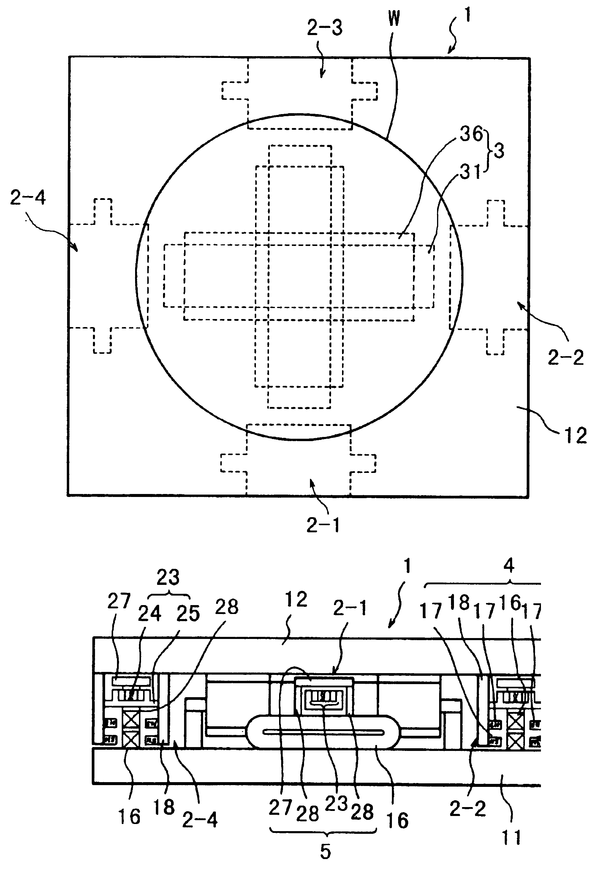
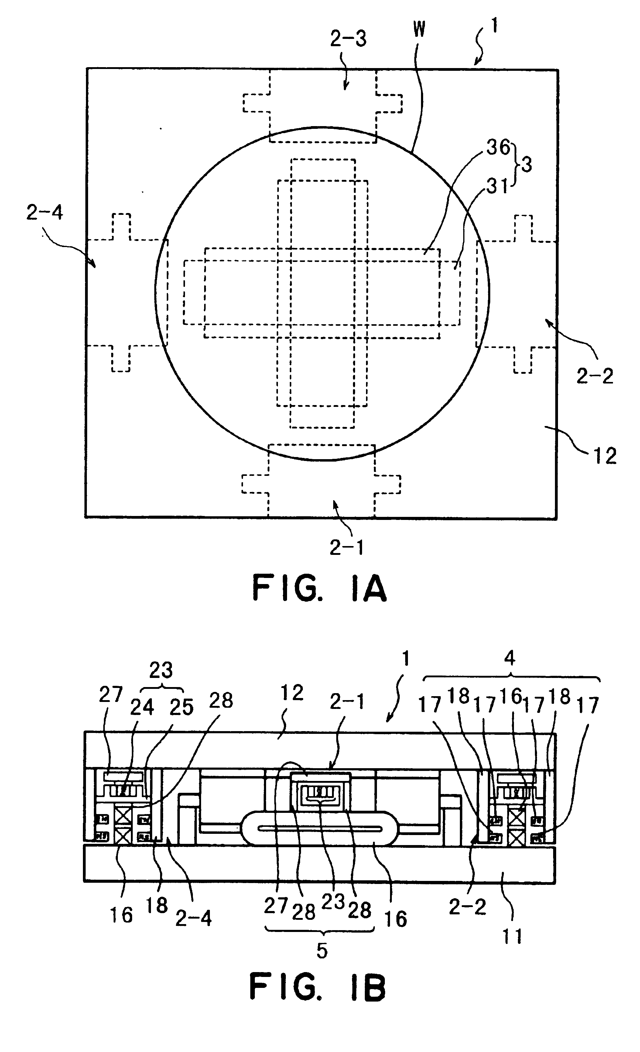
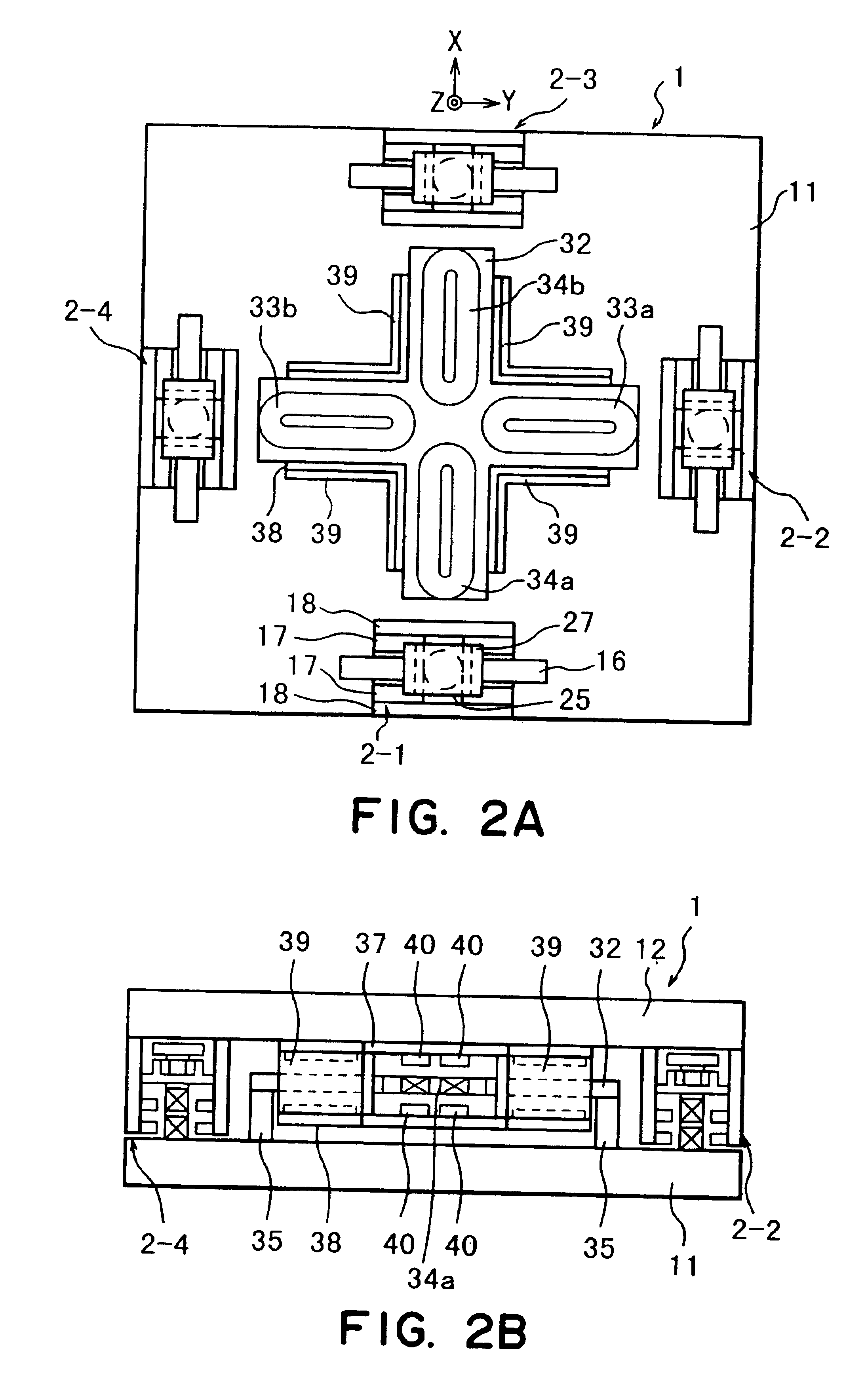
[0082]FIGS. 1A, 1B, 2A and 2B show a fine-motion stage of a supporting system according to a first embodiment of the present invention, wherein FIG. 1A is a top plan view, FIG. 1B is a front view wherein a yoke of a Z linear motor is demounted, FIG. 2A is a top plan view wherein a wafer stage top plate is demounted, and FIG. 2B is a front view wherein a Z suspension driving unit 2-1 is demounted. The fine-motion stage 1 of the supporting system is mounted on an X stage top plate 11 and it functions to position a wafer W (workpiece) with respect to six axial directions of X, Y, Z, tilt and θ. By means of four Z suspension driving units 2-1 to 2-4 provided at the peripheral portion, a wafer stage top plate 12 (carrying member) is supported and positioned with respect to the Z tilt direction. Also, by means of an X-Y-θ driving unit 3 provided at the central portion, the wafer stage top plate 12 is positioned with respect to the X, Y and θ directions. The wafer stage t...

second embodiment

[Second Embodiment]

[0093]FIGS. 4A and 4B show a fine-motion stage of a supporting system according to a second embodiment of the present invention, wherein FIG. 4A is a front view in a state in which a yoke in front of a Z linear motor is demounted, and FIG. 4B is an enlarged perspective view of that portion. In the fine-motion stage 1 of this supporting system, the lifting iron plate 27 of the first embodiment is replaced by an upper magnet unit 41 having an upper yoke 42 and upper magnets 43a and 43b. Also, the attracting magnet 23 of the first embodiment is replaced by a lower magnet unit 46, which comprises lower magnets 47a and 47b as well as a lower yoke 48. The upper magnets 43a and 43b and the lower magnets 47a and 47b are magnetized so that they attract each other. In the first embodiment, the combination of the iron plate 27 and the magnet 23 is used to assure the attracting function as well as the freedom (release) along the plane perpendicular to the attracting direction...

third embodiment

[Third Embodiment]

[0095]FIGS. 5A and 5B show a fine-motion stage of a supporting system according to a third embodiment of the present invention, wherein FIG. 5A is a front view in a state in which a yoke in front of a Z linear motor is demounted, and FIG. 5B is an enlarged perspective view of that portion. In the fine-motion stage 1 of this embodiment, the magnet structure is similar to that of the second embodiment, and it comprises an upper magnet unit 41 having an upper yoke 42 and upper magnets 43a and 43b, as well as a lower magnet unit 46 having lower magnets 47a and 47b and a lower yoke 48. There is a difference held between them, with respect to the size along a plane perpendicular to the floating force producing direction. This embodiment differs from the second embodiment in that the upper magnets 43a and 43b and the lower magnets 47a and 47b are magnetized so as to produce a mutually repulsive force, and thus, a repulsive magnet unit 49 is provided. The coupling relation...


PUM

PropertyMeasurementUnit
current frequencyaaaaaaaaaa
resisting forceaaaaaaaaaa
forceaaaaaaaaaa

Abstract

An exposure apparatus includes a carrying member for carrying thereon a workpiece and a supporting mechanism having a magnet, for supporting a weight of the carrying member. A force to be applied to the magnet does not change with a shift of the carrying member along a plane perpendicular to a direction in which the weight is supported.

Description

[0001]This application is a divisional application of U.S. patent application Ser. No. 09 / 784,054, filed Feb. 16, 2001, now U.S. Pat. No. 6,665,053.FIELD OF THE INVENTION AND RELATED ART[0002]This invention relates to a supporting system suitably usable, for example, in a fine-motion stage of a wafer stage incorporated into a semiconductor exposure apparatus.[0003]FIG. 28 is a perspective view of a wafer rough-motion stage of a supporting system used in a semiconductor exposure apparatus. In this wafer rough-motion stage, a Y yaw guide 202 is fixed on a base table 201, and a Y stage 203, which is guided by a side face of the Y yaw guide 202 and a top face of the base table 201 is slidably supported on the base table 201 by means of an air slide (not shown) along a Y direction. The Y stage 203 consists mainly of four components, that is, two X yaw guides 204, a Y large slider 205 and a Y small slider 206. The Y large slider 205 is opposed to the side face of the Y yaw guide 202 and t...

Claims


Application Information

Patent Timeline
Patent Type & Authority Patents(United States)
IPC IPC(8): G03F7/20H01L21/67H01L21/68G12B5/00G03B27/58H01L21/027H02N15/00
CPCF16C39/06G03B27/58G03F7/70691H01L21/682H02N15/00
Inventor KORENAGA, NOBUSHIGE
Owner CANON KK
Why Eureka
Try Eureka