Image forming apparatus

a technology of forming apparatus and fixing device, which is applied in the direction of electrographic process apparatus, instruments, optics, etc., can solve the problem that the temperature of the fixing device may not be able to rise in an assumed time period completely

Inactive Publication Date: 2005-10-04
CANON KK
View PDF10 Cites 4 Cited by
  • Summary
  • Abstract
  • Description
  • Claims
  • Application Information

AI Technical Summary

Benefits of technology

[0010]The present invention has been devised in view of the above and other drawbacks, and it is an object of the present invention to provide an image forming apparatus provided with a heat-fixing device, which can perform image formation and temperature rising of the fixing device in parallel in order to make FPOT shortest and can perform temperature rising of the fixing device appropriately without imposing any load to components of the image forming apparatus even if the temperature rising of the fixing device is not in time for the image formation.
[0014]The fixing means is preferably a quick start fixing device with a short warm-up time.
[0017]In the image forming apparatus in accordance with the present invention, in particular, the image forming apparatus provided with the quick start fixing device, image formation and temperature rising of the fixing device are performed in parallel in order to make FPOT shortest and, if the temperature rising of the fixing device is not in time for the image formation, image forming operations such as the rotation of the developing roller and the rotation of the photosensitive drum are performed after the fixing device has reached a predetermined temperature. Thus, the temperature rising of the fixing device can be performed appropriately without affecting usable lives of components of the image forming apparatus such as a developing device and the photosensitive drum.
[0020]It is another object of the present invention to provide an image forming apparatus that is provided with a heat-fixing device and performs image formation and temperature rising of the fixing device in parallel, wherein FPOT becomes shortest by appropriately judging a temperature rising state of the fixing device in every situation and allowing a temperature of the fixing device to rise to an appropriate temperature in a shortest time.
[0028]That is, the present invention is an image forming apparatus consisting of a first sequence for controlling a temperature of the developing device and a second sequence for forming an image on a material to be recorded, wherein a temperature rising situation of the fixing means of the fixing device is detected to calculate a temperature rising curve and determine start-up timing of the second sequence, whereby a temperature rising state of the fixing device for determining the start-up timing of the second sequence can be accurately judged in every situation and FPOT always becomes shortest.
[0029]In the image forming apparatus in accordance with the present invention, in particular, the image forming apparatus that is provided with the quick start fixing device and performs image formation on a material to be recorded and temperature rising of the fixing device in parallel, a temperature rising state of the fixing device can be appropriately judged in every situation from a temperature rising curve of the fixing device. Thus, an image forming apparatus in which FPOT becomes shortest under every situation can be provided. In addition, since unnecessary heating of the fixing device can be controlled, the present invention is also effective for energy saving.

Problems solved by technology

However, in such a case, for example, where an image forming apparatus is placed under a low temperature environment or where a voltage of a power supply to the image forming apparatus has dropped to a lower limit value, temperature of the fixing device may not be able to completely rise in an assumed time.

Method used


Image

  • Image forming apparatus
  • Image forming apparatus
  • Image forming apparatus

Examples


first embodiment

[0051]An image forming apparatus in accordance with a first embodiment of the present invention will be described with reference to FIGS. 1 to 6.

Overall Structure

[0052]First, an overall structure of the image forming apparatus will be briefly described with reference to FIG. 1.

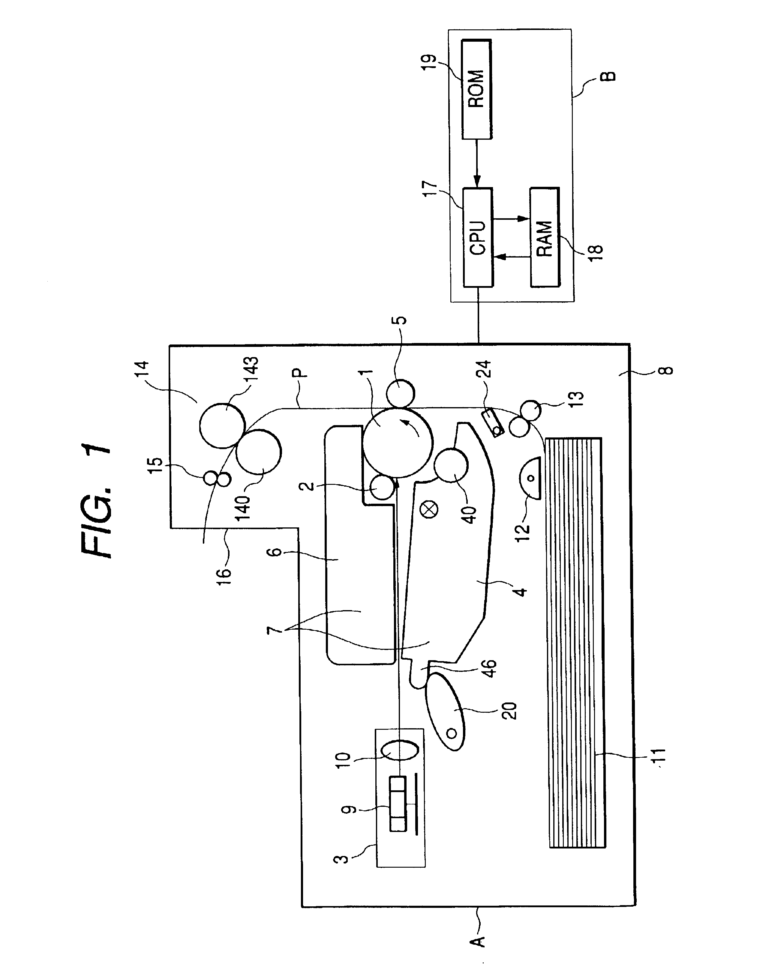
[0053]FIG. 1 is a vertical sectional view showing an overall structure of a laser beam printer A that is a form of the image forming apparatus.

[0054]A photosensitive drum 1 as an image bearing body is driven to rotate counterclockwise by driving means (not shown) as indicted by an arrow in the figure. A charging device 2 for uniformly charging the surface of the photosensitive drum 1, a scanner unit 3 for irradiating a laser beam L based on image information to form an electrostatic latent image on the photosensitive drum 1, a developing device 4 for applying toner to the electrostatic latent image to develop it as a toner image, a transfer roller 5 for transferring the toner image on the photosensitive drum 1...

second embodiment

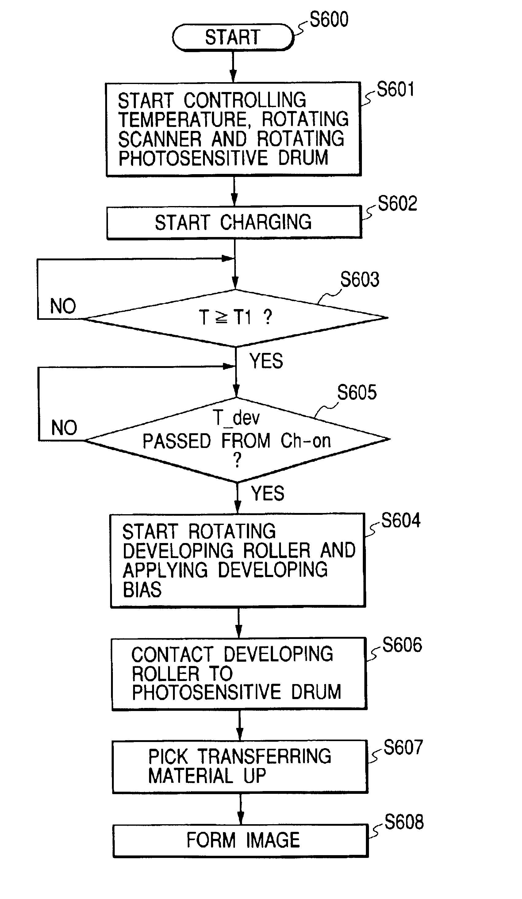
[0091]Image forming operations in accordance with a second embodiment of the present invention will be described in detail with reference to FIGS. 1, 7 and 8. FIG. 7 is a timing chart representing operations of an image forming apparatus in accordance with the second embodiment. FIG. 8 is a flow chart representing operations of the image forming apparatus in accordance with the second embodiment. Note that parts having the same structure and actions as those in the first embodiment are denoted by the identical reference numerals, and the parts will not be described.

[0092]When operations of the image forming apparatus is started by input of a print signal in an image forming apparatus main body (Start, S800), first, the CPU 17 starts controlling fixing temperature for controlling the fixing device 14 to a predetermined temperature and rotation of the scanner 3 as a first sequence group (Heat-on, S801). In this embodiment, rotation of a photosensitive drum and application of a chargin...

third embodiment

[0096]Image forming operations in accordance with a third embodiment of the present invention will be hereinafter described. This embodiment is characterized in that a fixing device is preheated when operations of the image forming apparatus is stopped (at the time of standby) in the image forming apparatus of the first embodiment. Since the quick start fixing device of the electromagnetic induction heating system as in the first embodiment has a small thermal capacity of a heating member unlike the conventional fixing device of the heat roller system, it can be preheated with a slight electric power. Thus, in this embodiment, the fixing device is preheated to about 120° C. at the time of standby and usual heating is performed simultaneously with starting the image forming operations.

[0097]In this way, since the fixing device has already been heated to 120° C., temperature rising to a fixing temperature is quicker than rising temperature from a room temperature and timing for starti...


PUM


Abstract

In an image forming apparatus, a first sequence group operates after input of a print signal and a second sequence group is started up at timing when a temperature T of a fixing device has reached a certain temperature T1 after the input of the print signal or timing for which a temperature rising curve is calculated from a time for the temperature T to reach a certain temperature T2 from the temperature T1 during temperature rising of the fixing device. With this image forming apparatus, it becomes possible to reduce unnecessary operations of a developing device and a photosensitive drum and extend a usable life of the developing device even if image formation and temperature rising of the fixing device are performed in parallel.

Description

BACKGROUND OF THE INVENTION[0001]1. Field of the Invention[0002]The present invention relates to an image forming apparatus for forming and bearing an unfixed toner image on a material to be recorded with a transfer system or a direct system like electrofax by an appropriate image forming process such as an electrophotographic process, electrostatic recording process and a magnetic recording process and fixing the unfixed toner image on the material to be recorded by heat-fixing means.[0003]2. Related Background Art[0004]As fixing means in an image forming apparatus using an electrophotographic process, a fixing device of a film heating system has been put to practical use in response to a demand for energy saving. In the fixing device of the film heating system, a thin film having heat resistance is nipped between a ceramic heater as heat generating means and a pressure roller as a pressuring member to form a fixing nip. The fixing device applies heat and pressure to a material to ...

Claims


Application Information

Patent Timeline
Patent Type & Authority Patents(United States)
IPC IPC(8): G03G15/00G03G15/20
CPCG03G15/2003G03G15/50
Inventor UCHIYAMA, AKIHIKO
Owner CANON KK
Why Eureka
Try Eureka