Method for manufacturing perpendicular magnetic recording head having inverted trapezoidal main magnetic pole layer

a manufacturing method and magnetic recording technology, applied in the manufacture of head surfaces, manufacturing tools, instruments, etc., can solve the problems of difficult to improve the recording density in the longitudinal direction of the recording track, the magnetic field of the recording head cannot be clearly distributed for high density recording, and the increase of the pulse width of the reproduced waveform, etc., to achieve good recording and regeneration characteristics, clear magnetization distribution, and good recording

Inactive Publication Date: 2005-10-11
TDK CORPARATION
View PDF11 Cites 34 Cited by
  • Summary
  • Abstract
  • Description
  • Claims
  • Application Information

AI Technical Summary

Benefits of technology

[0016]Accordingly, it is an object of the present invention to solve the problems as hitherto described by providing a method for manufacturing a perpendicular magnetic recording head which can suppress the occurrence of fringing on the recording pattern while improving the off-track performance, and which can improve the recording density in the longitudinal direction of the recording track (A-direction).
[0021]The inverted trapezoidal shape of the front face of the main magnetic pole layer on the opposing face permits the edge to be prevented from protruding out of the recording track even when the edge of the main magnetic pole layer forms a skew angle to the tangent of the travel direction of the recording medium during recording on the recording medium, thereby preventing fringing from appearing to improve off-track performance.
[0031]The magnetic domain boundaries of the recording track also become straight lines when the upper edge of the main magnetic pole layer is a straight line. Consequently, a clear distribution of magnetization may be attained even by increasing the recording density in the longitudinal direction of the recording track, thereby enabling good recording and regeneration characteristics to be obtained.

Problems solved by technology

As a result, the pulse width of the reproduced waveform is increased, and a clear distribution of the recording magnetic field cannot be obtained for high density recording.
Consequently, it becomes difficult to improve the recording density in the longitudinal direction of the recording track (the A-direction in the drawing).

Method used


Image

  • Method for manufacturing perpendicular magnetic recording head having inverted trapezoidal main magnetic pole layer
  • Method for manufacturing perpendicular magnetic recording head having inverted trapezoidal main magnetic pole layer
  • Method for manufacturing perpendicular magnetic recording head having inverted trapezoidal main magnetic pole layer

Examples


example

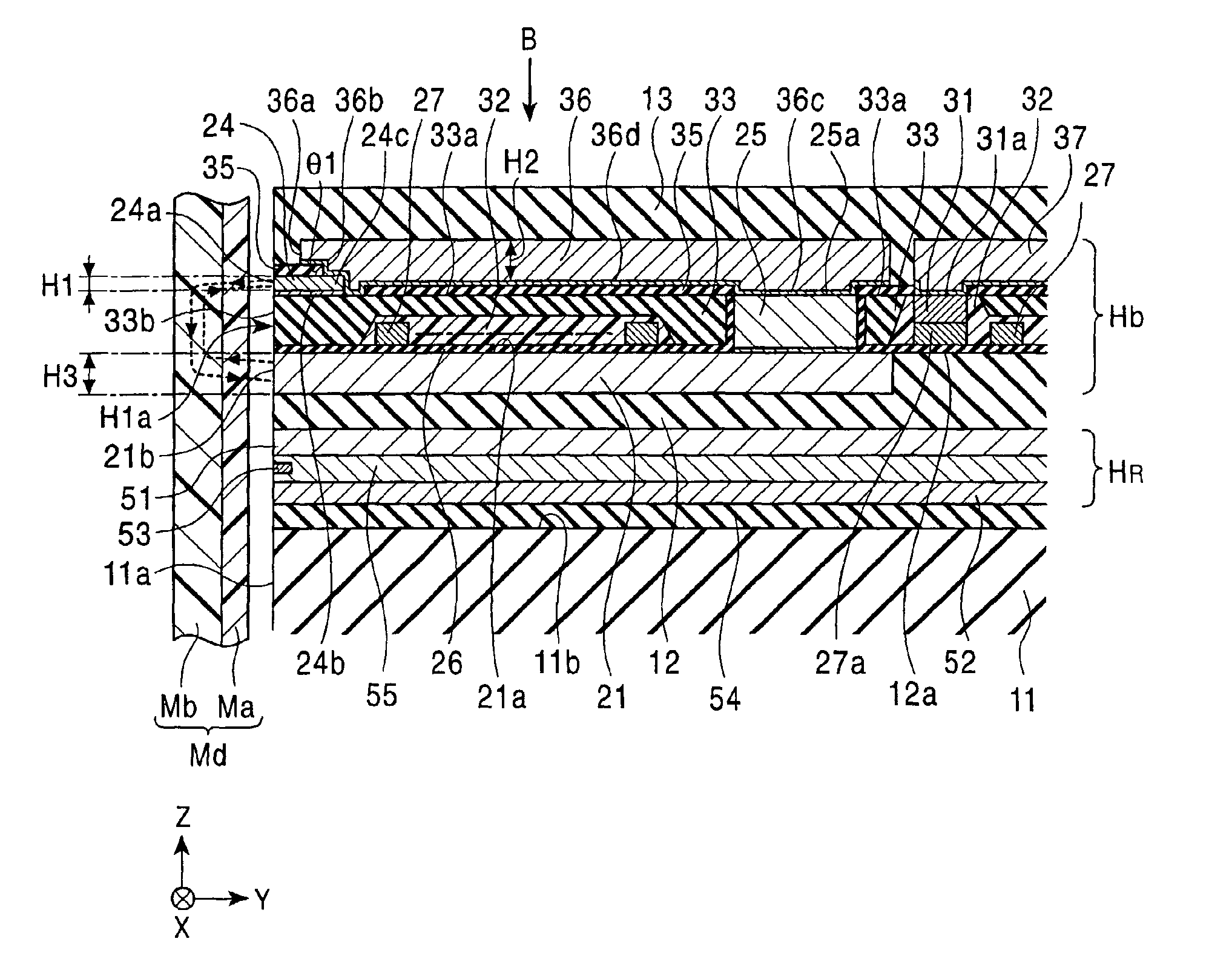
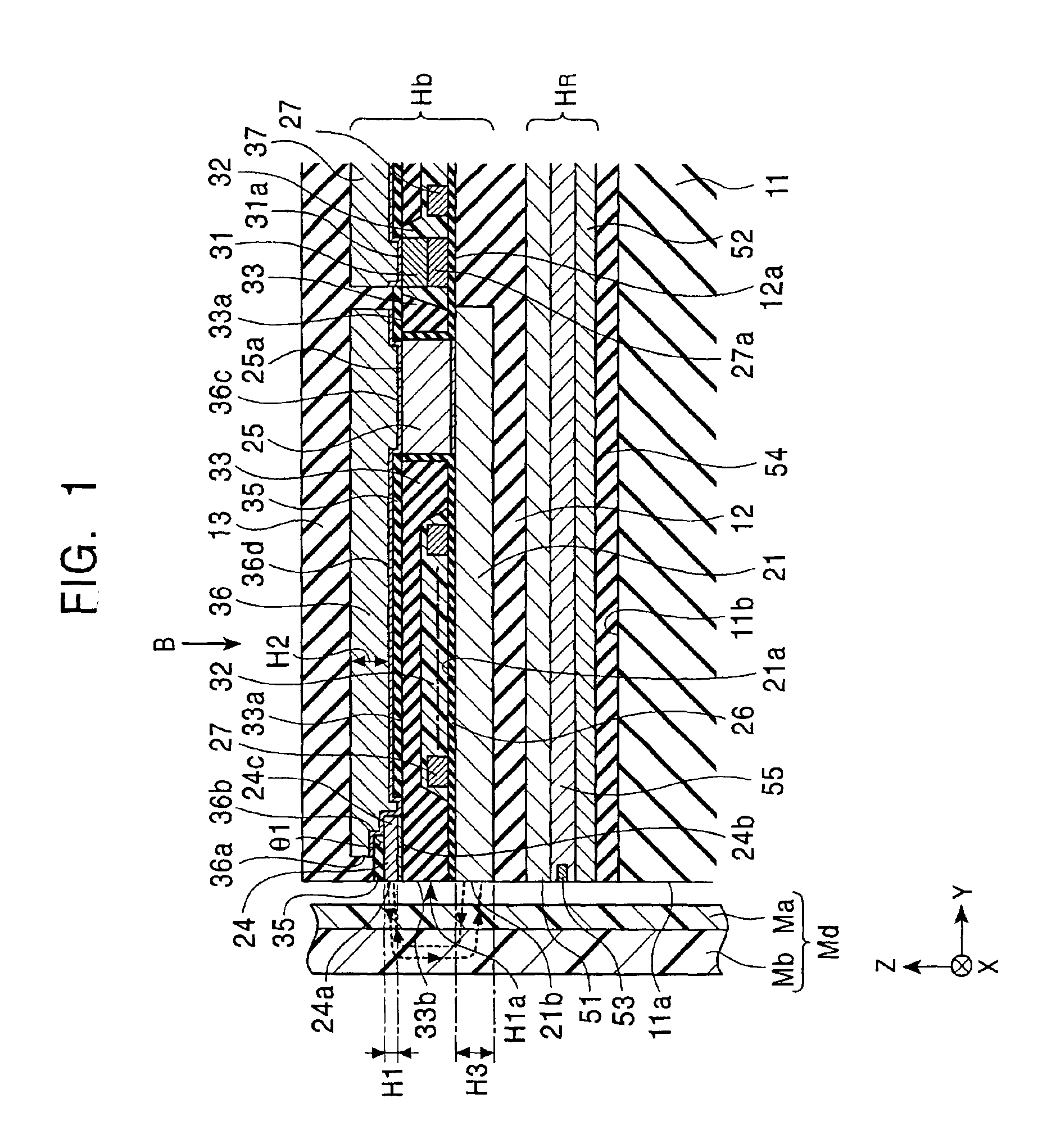
[0230]FIG. 37 shows a fragmentary cross section in the vicinity of the perpendicular magnetic recording head in the step shown in FIG. 18 or 22 in the embodiment of the foregoing manufacturing method according to the present invention.

[0231]An anisotropic ion-milling process is applied by irradiating milling particles from a direction inclined by a given angle θ8 (or θ9) relative to the center line C in the longitudinal direction of the main magnetic pole layer 24 from the upward shown in FIG. 37.

[0232]FIG. 38 is a graph showing the relation between the milling angle relative to the center line C in the longitudinal direction of the main magnetic pole layer 24 and etching rate.

[0233]The curve represented by a mark □ in the graph shows the etching rate in the height direction (the Y-direction in FIG. 37) of the main magnetic pole layer 24. The etching rate in the height direction of the main magnetic pole layer 24 depends on the milling angle relative to the center line C. The graph ...


PUM

PropertyMeasurementUnit
angleaaaaaaaaaa
angleaaaaaaaaaa
angleaaaaaaaaaa

Abstract

The side edge of the main magnetic pole layer is prevented from protruding in the track width direction even when a skew angle is generated by forming the main magnetic pole layer of the opposing face opposing the recording medium as an inverted trapezoid, thereby enabling the occurrence of side fringing to be prevented.

Description

BACKGROUND OF THE INVENTION[0001]1. Field of the Invention[0002]The present invention relates to a perpendicular magnetic recording head for recording on a magnetic recording medium such as, for example, a disk having a rigid film by applying a perpendicular magnetic field. More specifically, the object of the present invention is to provide a perpendicular magnetic recording head compatible with high density recording by suppressing the occurrence of fringing of recording patterns, and a method for manufacturing the magnetic recording head.[0003]2. Description of the Related Art[0004]A device for high density recording of magnetic data on a recording medium such as a disk has utilized a perpendicular magnetic recording method. FIG. 41 is a cross-sectional view showing the general structure of a perpendicular magnetic recording head to be used in the perpendicular magnetic recording method described above.[0005]The perpendicular magnetic recording head H used in the perpendicular ma...

Claims


Application Information

Patent Timeline
Patent Type & Authority Patents(United States)
IPC IPC(8): G11B5/127G11B5/31
CPCG11B5/1278G11B5/3163Y10T29/49032Y10T29/4906Y10T29/49043Y10T29/49044Y10T29/49052Y10T29/49046Y10T29/49048
Inventor SATO, KIYOSHI
Owner TDK CORPARATION
Why Eureka
Try Eureka