[0011]By using a plastic tube according to the invention, the work which must be carried out at the
consumer's facility is considerably reduced, whereby a plastic tube which has been prefabricated according to the invention is not substantially more expensive than the tubes which are already known because plastic tubes according to the invention can be manufactured in several parallel webs in the context of the
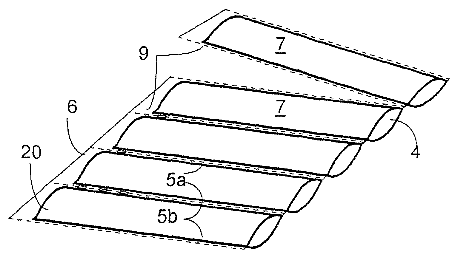
prefabrication, for example with doubled width. The only remaining step is then to blow gas laterally into the filling bodies, and to close the lateral gas filling opening with a welded seam in the longitudinal direction of the tube. As a result, the device of
machine for the manufacture of gas filled bodies, on the one hand, can be designed more simply, and, on the other hand, it can be easily adapted to the manufacture of filling bodies of different sizes. The separation of the upper sheet and the lower sheet by means of a tool is not absolutely required. This separation is achieved by inflation with gas. Because the gas filling is carried out from a longitudinal edge, and also because only one
welding device needs to be provided, which is also arranged at this longitudinal edge and which needs only to be designed for the
welding of the gas filling opening, plastic tubes of different width can be processed without any problem. No work needs to be done over the width of the
plastic film, so that the corresponding device parts, such as, for example, perforation knives and corresponding welding tools, also are not present, and therefore they do not have to be adapted or exchanged. The dimensions of the filling bodies in the longitudinal direction of the tube also can be changed without any problem because either always only one gas filling opening of identical width needs to be closed or the corresponding welding tool can be exchanged in a very simple manner. The welding tool is accessible without problem because no additional tools are present in the immediate proximity. A device according to the invention is therefore more cost advantageous and also more maintenance friendly than known devices. One only needs to produce a welded seam, and always at the same place, so that variations in the quality of the welded seam are reduced and a stable high level of welding quality is guaranteed.
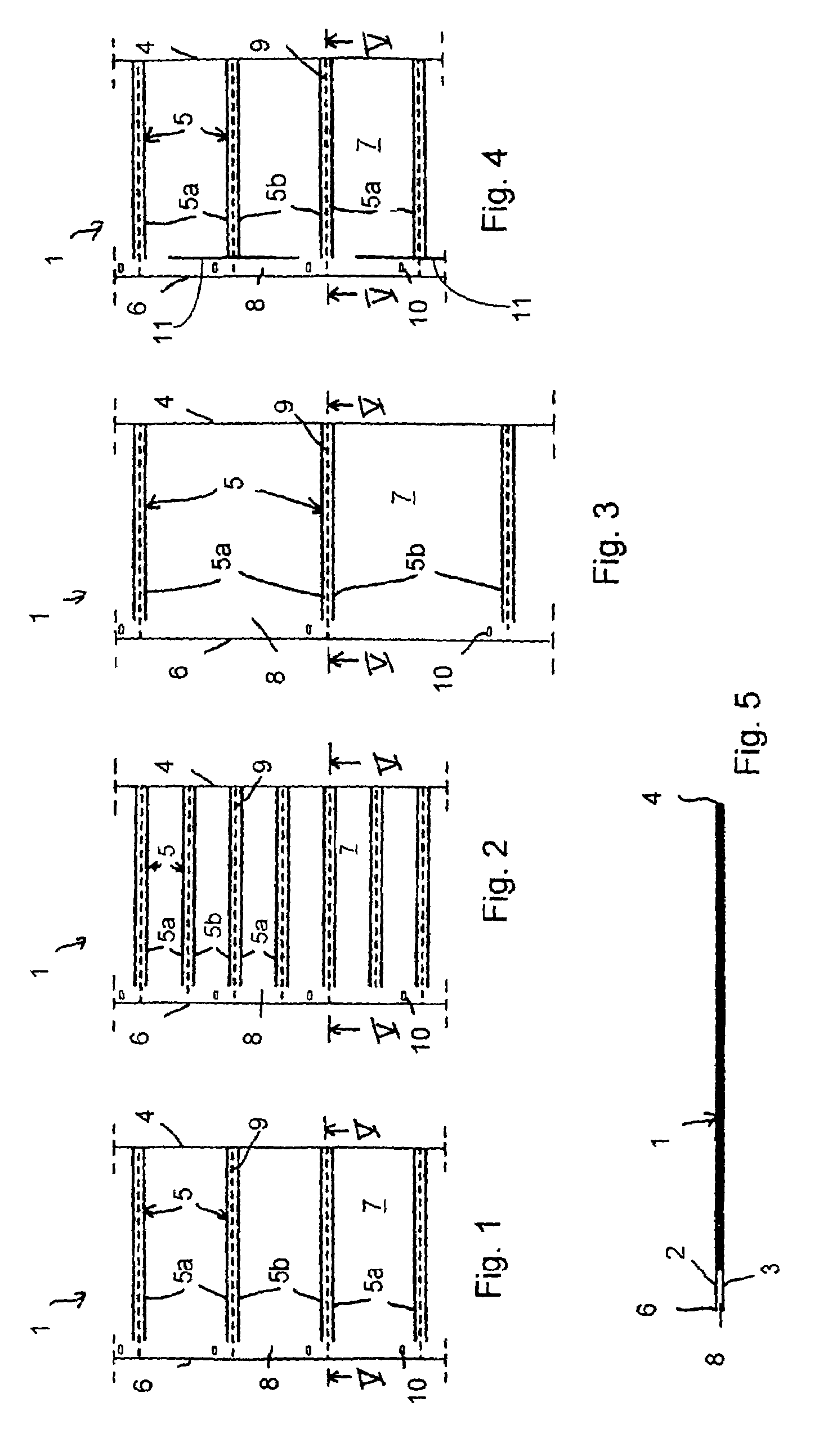
[0013]In an advantageous embodiment, a perforation is arranged in the
intermediate space of each pair of welded seams, which allows a simple separation of the filled pouch. Alternately, the separation of the pouches can also be carried out by a
cutting knife or a
cutting edge which is provided at the device for filling the plastic tubes.
[0014]Advantageously, in the space between the second longitudinal edge and the adjacent ends of the transversely running welded seams, markings for indicating the position of these welded seams are arranged. With these measures, one avoids having to use an expensive synchronization which otherwise would be required. The markings are preferably formed as punched out sections, although they could also be printed in a manner which is also preferred.
[0016]In an additional advantageous variant of the invention, punched out sections are provided in the area of the perforation, at least in proximity to the longitudinal edges, to allow the engagement of a pin for the continued transport of the tube. The plastic tube can thus be led in a simple manner through the device.
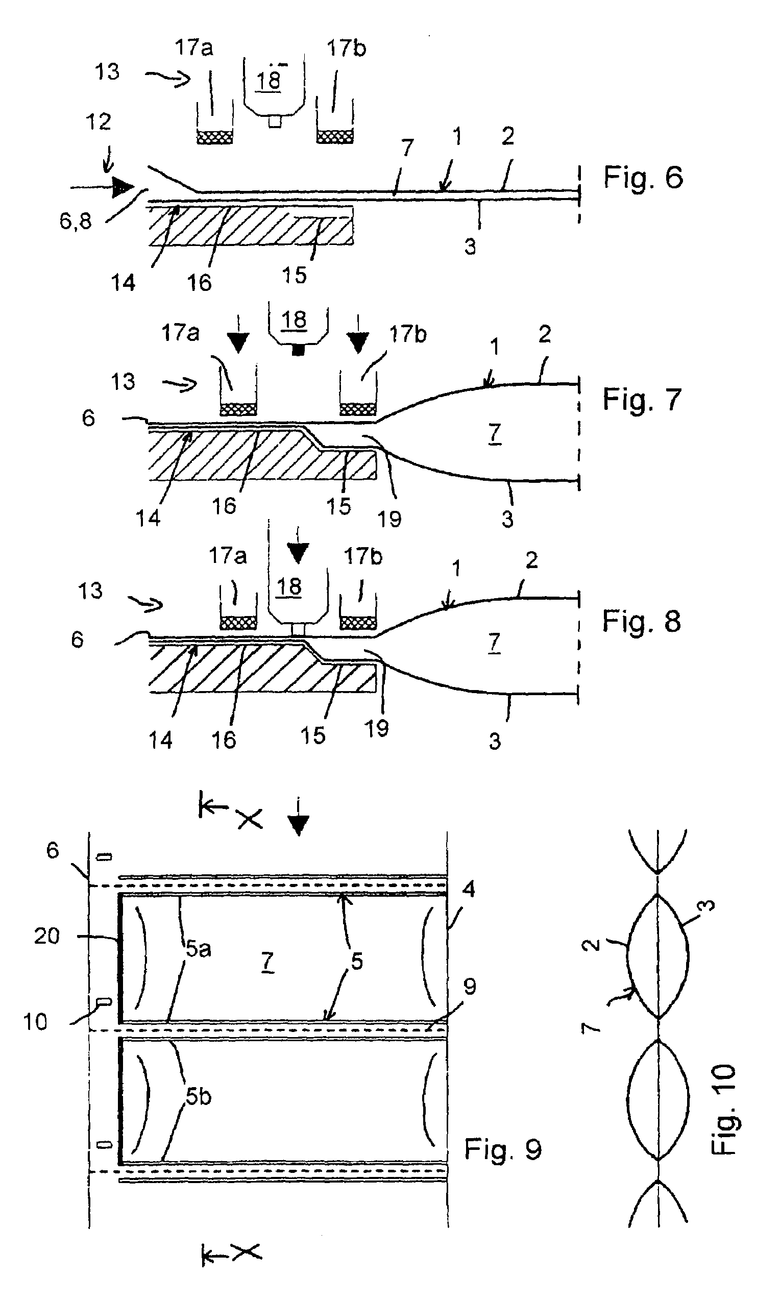
[0018]In the case of a device according to the invention, it is preferred that the
nozzle can be introduced into the gas filling opening of each pocket, where it is particularly preferred not to provide a seal between the
nozzle and the edge of the filling opening. This results in more cost reductions, although it is not possible to achieve high filling pressures due to leakages.
[0025]In this embodiment it is also conceivable in each case to simultaneously fill or weld several pockets, preferably two pockets next to each other, for the purpose of increasing the
operating speed.

