Control scheme and method for dehumidification systems at low ambient conditions

Active Publication Date: 2005-10-18
CARRIER CORP
View PDF9 Cites 14 Cited by
  • Summary
  • Abstract
  • Description
  • Claims
  • Application Information

AI Technical Summary

Benefits of technology

[0012]According to the invention, a method is provided for operating a vapor compression system, which method comprises the steps of providing a vapor compression system having a compressor circuit including a compressor having an inlet port and an outlet port, a circuit incorporating said compressor, a condenser, an evaporator and an expansion device for sequentially generating a cooling refrigerant for cooling a stream of air so as to provide a dehumidified cooled stream of air, and a reheat refrigerant for heating said dehumidified cooled stream of air to provide a reheated dehumidified stream of air; and controlling discharge pressure from said compressor outlet port whereby discharge pressure is increased, and two-phase flow of refrigerant to said expansion device and evaporator freeze-up can be avoided. Additionally, the system dehumidification performance is enhanced through a boost o

Problems solved by technology

At low ambient conditions, the foregoing methods can result in undesirable two-phase flow at the inlet of the expansion device of the system as well as evaporator freeze-up.
Furthermore, when operating at low

Method used


Image

  • Control scheme and method for dehumidification systems at low ambient conditions
  • Control scheme and method for dehumidification systems at low ambient conditions
  • Control scheme and method for dehumidification systems at low ambient conditions

Examples


Embodiment Construction

[0019]The invention relates to a vapor compression system and method for operating same wherein dehumidification is allowed at low ambient conditions while avoiding two-phase flow to the expansion device, avoiding evaporator coil freeze-up and improving overall system dehumidification efficiency and reliability.

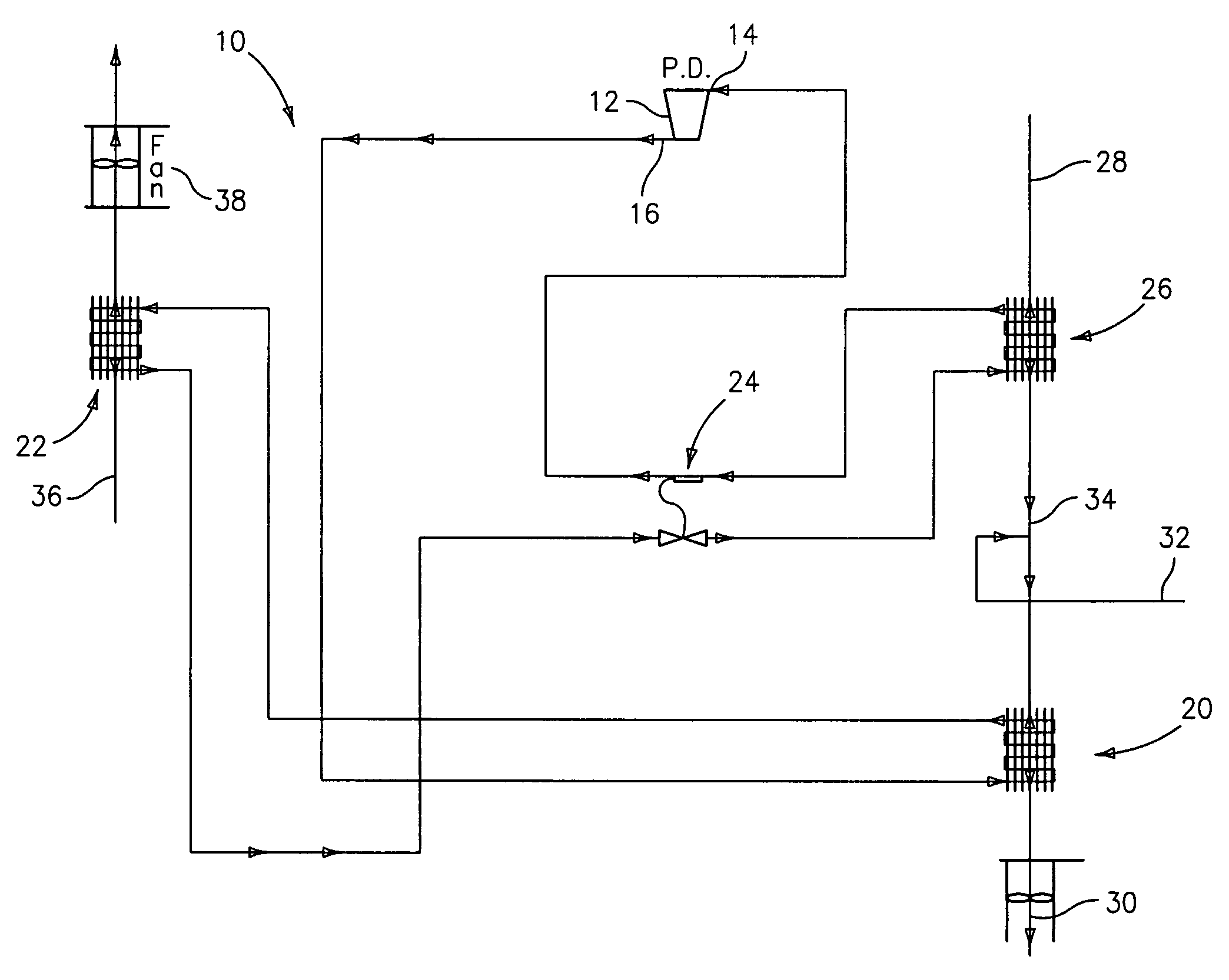
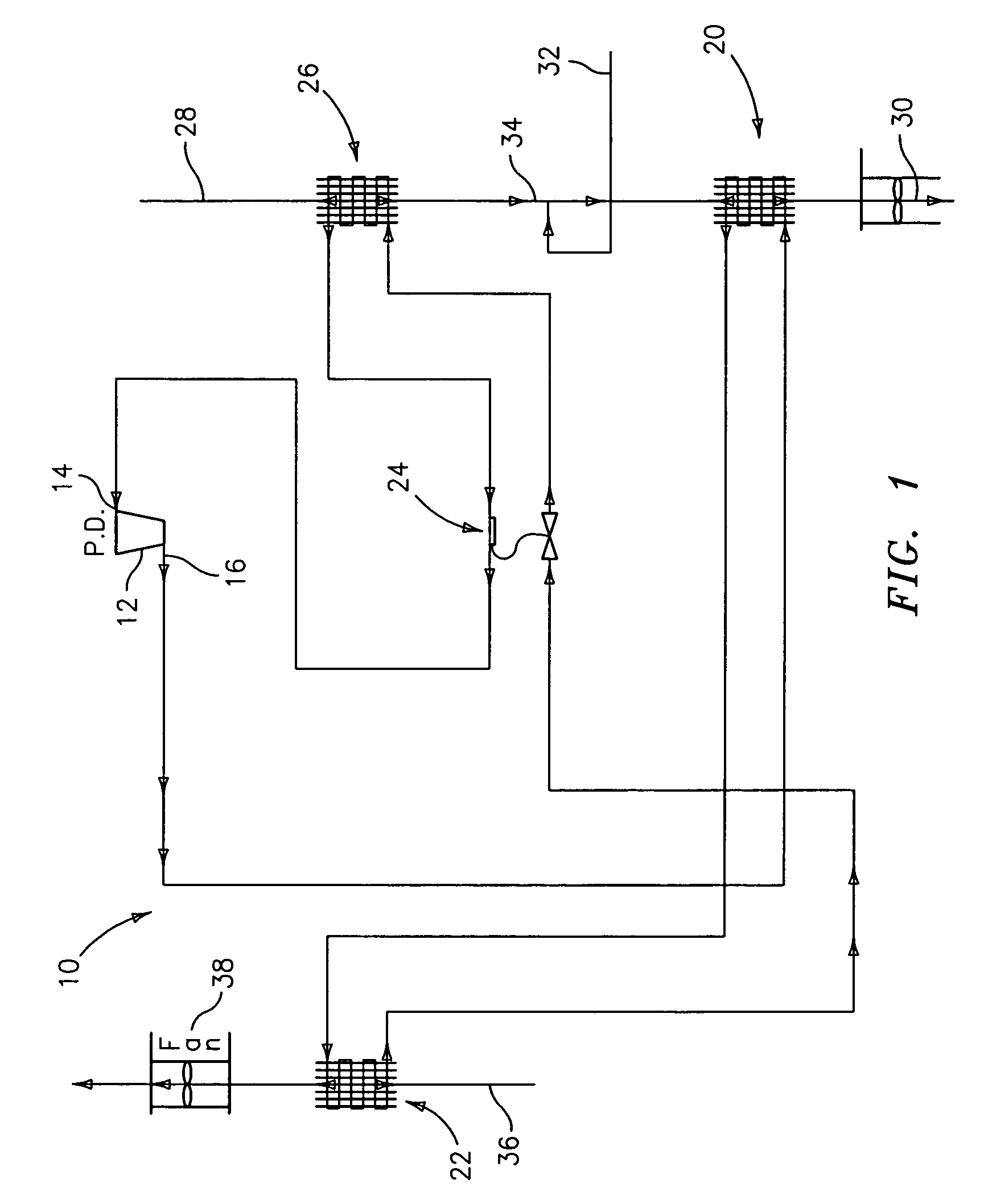
[0020]FIG. 1 shows a system 10 in accordance with the present invention which includes a compressor 12 having an inlet port 14, an outlet port 16 and refrigerant lines which lead in series to a plurality of components including a reheat coil 20 for reheating of overcooled and dehumidified indoor air, a main condenser 22 for cooling refrigerant with outside air, expansion device 24, evaporator 26 for cooling and dehumidifying of indoor air and back to inlet port 14 of compressor 12.

[0021]When system 10 is operated in a dehumidification mode, indoor air 28 is passed through evaporator 26 and cooled so as to remove moisture. This can frequently result in air which is cooled beyo...


PUM


Abstract

A method for operating a vapor compression system includes the steps of providing a vapor compression system having a compressor circuit including a compressor having an inlet port and an outlet port, a circuit incorporating the compressor, a condenser, an evaporator and an expansion device for sequentially generating a cooling refrigerant for cooling a stream of air so as to provide a dehumidified cooled stream of air, and a reheat refrigerant for heating the dehumidified cooled stream of air to provide a reheated dehumidified stream of air; controlling discharge pressure from the compressor outlet so as to increase discharge pressure from the compressor outlet. Furthermore, system dehumidification performance is improved in terms of latent capacity boost, undesired sensible capacity reduction, latent efficiency enhancement, and recovery of supply air temperature to a desired level.

Description

BACKGROUND OF THE INVENTION[0001]The invention relates to vapor compression systems with enhanced dehumidification capability and, more particularly, to operation of such vapor compression systems to provide dehumidification at low ambient conditions and improvement of such operation.[0002]Operation of vapor compression systems to provide a dehumidification function of an indoor space along with minimum sensible cooling is sometimes necessary. This function is provided utilizing three main design approaches, each of which employs main refrigerant flow, or a portion thereof, for reheat of the dehumidified and overcooled air stream.[0003]The first concept uses compressor discharge gas re-routed to a reheat coil of the system which is placed in the indoor section behind the evaporator and connected sequentially with the main condenser. This allows reheat of the indoor air stream to reduce sensible capacity, after the air stream has been cooled to provide the desired dehumidification.[0...

Claims


Application Information

Patent Timeline
IPC IPC(8): F25B6/00F25B6/04F24F3/153F24F3/12F25B40/04F25B40/00
CPCF24F3/153F25B6/04F25B40/04F25B2400/0403F25B2500/31
Inventor TARAS, MICHAEL F.DOBMEIER, THOMAS J.BUSSJAGER, RUDDY C.
Owner CARRIER CORP
Why Eureka
Try Eureka