Charge-injected internal combustion engine, and method of operating same

a technology of internal combustion engine and fuel injection, which is applied in the direction of engine starters, electric control, machines/engines, etc., can solve the problems of reducing starting performance, inability to quickly provide compressed air at a sufficient pressure to convey fuel within the cylinder, and small volume of compressed air discharged from air compressors, so as to achieve improved fuel efficiency and superior starting performance

Active Publication Date: 2005-10-18
ORBITAL ENGINE CO PTY LTD
View PDF3 Cites 21 Cited by
  • Summary
  • Abstract
  • Description
  • Claims
  • Application Information

AI Technical Summary

Benefits of technology

[0012]In order to resolve the difficulties encountered in the known charge-injected engines, it is an object of the present invention to provide a charge-injected internal combustion engine with superior starting performance, using straightforward controls. It is a further object of the invention to economically produce a charge-injected engine, and it is yet another object to produce a charge-injected engine with improved fuel efficiency.

Problems solved by technology

However, at the time of starting up the internal combustion engine described in Japanese Patent Publication No. 2000-514150, and in particular, directly after the beginning of engine startup, the volume of compressed air discharged from the air compressor is small.
Therefore, when the pressure of the compressed air within the air duct falls to ambient pressure, due to the internal combustion engine having been stopped for a long time, it is not possible to quickly provide compressed air at a sufficient pressure to convey the fuel within the cylinder.
Because the air flow of compressed air to the fuel injection unit is weak, it becomes difficult for the fuel to be atomized, combustibility falls, and starting performance is therefore lowered.
However, in the related technology, when the engine has not yet reached operating speed, compressed air at the time of the compression stroke bleeds outwardly from the cylinder via the fuel injection unit.
The pressure within the cylinder therefore falls, and the starting performance of the internal combustion engine deteriorates.
Control of the fuel injection unit therefore becomes complex, and cost is increased, in cases where a pressure sensor is required to detect the pressure within the intake air duct.
Moreover, as there is a small amount of oil mixed in with the air within the cylinder bore, when the compressed charge from the cylinder bore flows outwardly from the cylinder in the reverse direction from normal flow, this oil adheres to, or accumulates as a deposit on the walls of an air passage within the fuel injection unit, and interferes with the flow of the compressed air.

Method used


Image

  • Charge-injected internal combustion engine, and method of operating same
  • Charge-injected internal combustion engine, and method of operating same
  • Charge-injected internal combustion engine, and method of operating same

Examples


Embodiment Construction

[0038]In the following discussion, descriptions of selected illustrative embodiments of the present invention are given, with reference to the drawings. It should be understood that the following description is intended to illustrate, rather than to limit the invention. Herein, only structures considered necessary for clarifying the present invention are described. Other conventional structures, and those of ancillary and auxiliary components of the system, are assumed to be known and understood by those skilled in the art.

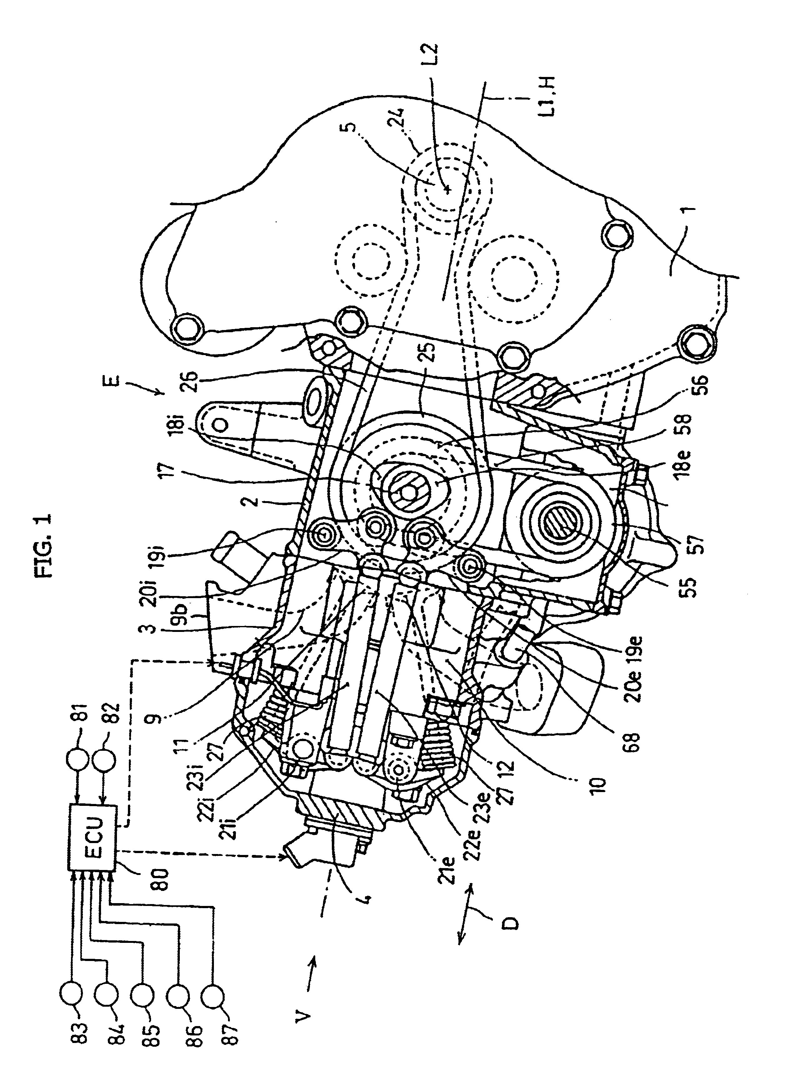
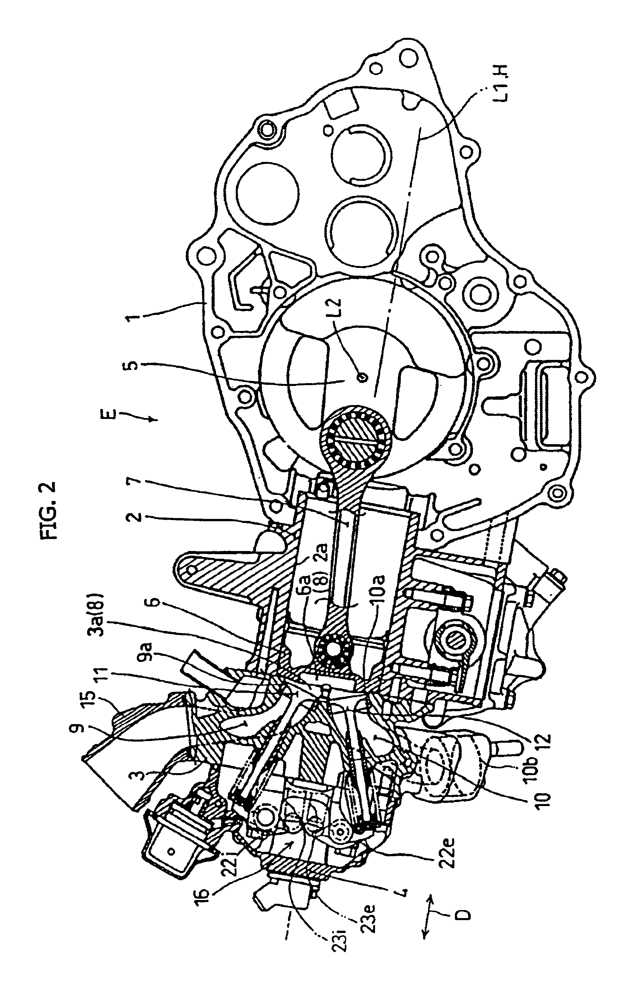
[0039]Referring now to FIGS. 1 to 3, a charge-injected internal combustion engine E, to which a first selected illustrative embodiment of the present invention is applied, is a water-cooled, single-cylinder four-stroke internal combustion engine. The engine E is adopted to be mounted on a vehicle such as a motorcycle, and is equipped with an engine body comprised of a crankcase 1 forming a crank chamber housing a crankshaft 5, a cylinder 2 connected to an upper en...


PUM


Abstract

A charge-injected internal combustion engine exhibits improved starting performance with charge-injection timing control. A charge-injected internal combustion engine has an air-fuel injection valve for directly injecting a compressed air-fuel mixture into a combustion chamber. The engine is also provided with an air pump, driven by the crankshaft for discharging compressed air, and a timing controller for setting injection timing of the air-fuel injection valve. When initial startup of the engine is detected, the controller sets the injection timing to the intake stroke. When the engine reaches a predetermined engine speed, or when the pressure of the injection air reaches a threshold pressure where injection of the air-fuel mixture is possible on the compression stroke, the timing controller switches the injection timing from the intake stroke to the compression stroke.

Description

CROSS-REFERENCE TO RELATED APPLICATIONS[0001]The present application claims priority under 35 USC 119 based on Japanese patent application No. 2003-138235, filed May 16, 2003.BACKGROUND OF THE INVENTION[0002]1. Field of the Invention[0003]The present invention relates to a charge-injected internal combustion engine equipped with a charge injection valve, for injecting a premixed air-fuel charge into a combustion chamber. More particularly, the present invention relates to a charge-injected internal combustion engine in which combustion air is compressed by an air pump driven by the engine crankshaft.[0004]2. Background Art[0005]A limited number of charge-injected internal combustion engines have previously been known. For example, a charge-injected engine is disclosed in Japanese Patent Publication No. 2000-514150. This internal combustion engine is equipped with an air-fuel injection unit for injecting a premixed air-fuel mixture directly into a combustion chamber, and an air compr...

Claims


Application Information

Patent Timeline
Patent Type & Authority Patents(United States)
IPC IPC(8): F02D41/06F02B61/00F02B33/02F02D41/40F02B33/06F02M67/12F02M67/00F02M67/02F02M69/04F02B61/02F02N17/08F02N17/00F02B23/10F02D41/04F02N19/00
CPCF02B61/02F02D41/062F02D41/401F02B33/06F02M67/12F02M69/045F02M67/02F02D2041/3088Y02T10/44Y02T10/40
Inventor SUZUKI, MASATOSHITAKIZAWA, TSUYOSHIAKAMATSU, SHUNJIURAKI, MAMORU
Owner ORBITAL ENGINE CO PTY LTD
Why Eureka
Try Eureka